Italia 800 906 907 | Internazionale +39 022 333 1521 | Benvenuti sul nostro nuovo sito web. Avete riscontrato un problema o un bug? Segnalatelo qui.



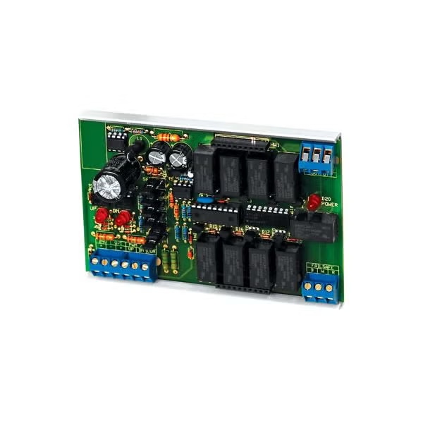
DRN3
Dispositivo di interfaccia da PWM/Analogico/Punto mobile a uscita di resistenza
- Converte i segnali di controllo in uscita di resistenza: i moduli DRN3.1 accettano ingressi analogici, a impulsi, a virgola mobile e a triac e li convertono in un'uscita resistiva proporzionale.
- Ideale per gli aggiornamenti dei controlli legacy: sostituisce direttamente i controller a resistenza variabile simulando un filo scorrevole o un potenziometro rotativo.
- Compatibilità di ingresso flessibile: supporta segnali di controllo 0-5 V CC, 0-10 V CC, 0-15 V CC, 0-20 mA, 4-20 mA, a impulsi e a virgola mobile.
- Opzioni di rete a resistenza multipla: le reti di resistori disponibili includono gli intervalli 0-135 Ω, 0-270 Ω, 0-500 Ω, 0-1K Ω, 0-10K Ω, 0-15K Ω e 0-20K Ω.
- Funzionamento failback affidabile: i relè failback integrati consentono al circuito di tornare al segnale originale del controller in caso di interruzione dell'alimentazione.
- Costruito per la simulazione di attuatori e sensori: ben adatto per applicazioni con potenziometri elettronici, controllo di attuatori elettrici e simulazione di sensori resistivi.
- Protezione dell'uscita senza avvolgimento: l'uscita della resistenza si arresta al valore minimo o massimo selezionato invece di avvolgersi, contribuendo a mantenere un controllo prevedibile.
- Design adatto ai pannelli: il montaggio compatto su guida a scatto, i terminali a vite imperdibili e l'adattatore per guida DIN opzionale consentono un'installazione ordinata sul pannello di controllo.
- Prestazioni dell'interfaccia durevoli: i relè Form C, la risoluzione di uscita a 256 passi, la conformità RoHS2/RAEE e la garanzia limitata di due anni di ACI garantiscono un utilizzo affidabile a lungo termine.
DRN3
Da


Panoramica del Prodotto
- Corrente in ingresso Da 4 a 20 mA, da 0 a 20 mA
- Nota sulla tensione di ingresso 0 a 5 Vcc, 1 a 5 Vcc, 0 a 10 cc, 2 a 10 Vcc, 0 a 15 Vcc, 3 a 15 Vcc @ 10.000Ω
- Temperatura di esercizio, max 120 °F
- Temperatura di esercizio minima 35 °F
- ID serie DRN3
- Temperatura di stoccaggio, max 150 °F
- Temperatura di stoccaggio, min. -20 °F
- Tensione di alimentazione 24 V CA/CC
Supported Applications
The ACI DRN3 series is an interface device designed to allow microprocessor control of a variable resistance. It directly replaces a variable resistance controller and simulates the action of a slide wire or rotary potentiometer. The unit accepts Analog, Pulse, or Floating Point input signals (including triac) and converts them into a proportional resistive output.
Operating Conditions & Performance
The DRN3 operates within an ambient temperature range of 35 to 120°F (1.7 to 48.9°C) with humidity between 10 to 95% non-condensing. Storage is supported from -20 to 150°F (-28.9 to 65.5°C). The device features a resolution of 256 Steps (No wrap around), and the time response full scale is about 6 seconds.
Input signal capabilities include:
- Voltage Signals: 0 to 5 VDC, 1 to 5 VDC, 0 to 10 VDC, 2 to 10 VDC, 0 to 15 VDC, and 3 to 15 VDC @ 10,000Ω.
- Current Signals: 0-20 mA and 4 to 20 mA @ 250Ω.
- Pulse Sources: Relay Contact Closure, Transistor, or Triac with signal levels of 7-30 VDC or 10-26.4 VAC @ 750Ω.
The unit is powered by 24 VAC +/- 10% or 24 VDC +25% / -8%, drawing a maximum of 250 mA supply current.
Fail-Safe and Digital Outputs
- Fail-Back: The DRN3.1 will automatically fail-back to 0 Ohms upon power loss; control reverts to the original controller signal if supply power is lost.
- Digital Output Type: Form "C" Relays with a contact rating of 2A @ 24 VDC and 0.5A @ 240 VAC.
Configuration Options
The series supports extensive configuration options for resistance output ranges, firmware versions, and mounting styles to accommodate specific control requirements.
Resistance Output Networks
Standard resistor networks are available in various ranges with specified wattage and tolerance:
- RN (0-135) Ω: 3W, 5% Tolerance
- RN (0-270) Ω: 3W, 5% Tolerance
- RN (0-500) Ω: 3W, 5% Tolerance
- RN (0-1K) Ω: 0.25W, 5% Tolerance
- RN (0-10K) Ω: 0.25W, 5% Tolerance
- RN (0-15K) Ω: 0.25W, 5% Tolerance
- RN (0-20K) Ω: 0.25W, 5% Tolerance
The series also supports custom resistance ranges upon request.
Firmware and Input Configuration
Different firmware versions support distinct pulse ranges and floating point rates of change:
- Version #1 (Chip 0052Y0H.HEX): Supports Pulse Ranges of 0.02-5.0s, 0.1-25.5s, or 0.59-2.93s; Floating Point Rates of Change at 30, 60, and 90 seconds.
- Version #2 (Chip 0054Y0B.HEX): Supports Pulse Ranges of 0.1 to 10.0s or 0.023 to 6.0s; Floating Point Rates of Change at 45, 120, and 240 seconds.
- Duty Cycle Version #4 (Chip 0305Y1A.HEX): Supports Pulse Range of 0.1 - 10 sec.
Housing and Mounting
The device features a Polyvinyl Chloride (PVC) snaptrack with UL94 V-0 flammability rating. Dimensions are (L) 5.00" x (W) 3.23" x (H) 1.00" (127.00 x 81.99 x 25.40 mm). Electrical connections utilize 45° Captive screw Terminal Blocks accepting wire sizes from 12 AWG to 22 AWG.
Accessories
- A/DRC 4.69 X 3.25: DIN Rail Adapter Kit for mounting flexibility.
- A/D0008 (142583): Transient Voltage Suppressor, Bi-directional, 56 VAC/DC, 1500W.
Key Product Differences
The DRN3 series is distinguished by its configurable input types and resistance output networks. The primary model variations are defined by the firmware version (Version #1 vs Version #2) which dictates supported pulse ranges and floating point rates of change.
- DRN3.1: Standard configuration with specific jumper settings for Analog, Pulse, or Floating Point inputs as detailed in the ordering grid.
- Resistor Networks (RN): Variants are identified by their resistance range (e.g., RN 0-1K vs RN 0-20K) and wattage ratings. Custom ranges outside standard tables require direct consultation with ACI.