


Cooling towers remove heat by bringing air and water into direct contact. Water is pumped to the top of the tower, distributed across a series of baffles, and exposed to moving air. As the water cools, some of it evaporates, so makeup water must periodically be added to maintain the proper operating level.
The cooled water collects in a basin beneath the tower or in a nearby sump. These basins are typically open to the atmosphere, less than four feet deep, and constructed from fiberglass, metal, or concrete.
How Ultrasonic Level Measurement Works
An ultrasonic level sensor sends a short, high-frequency sound pulse toward the water surface. The pulse reflects from the surface and returns to the sensor.
The sensor measures the time required for the echo to return, known as the time of flight. It then converts that measurement into the distance between the sensor and the water surface. Based on the configured measurement span, the sensor produces a proportional 4-20 mA output.
This signal can be connected to a controller, pump system, valve, or building-management system for automatic level control.
Cooling Tower Basin: Ultrasonic Level Detection
This diagram highlights how ultrasonic level transmitters are used to monitor and maintain proper water levels in an evaporative cooling tower basin.
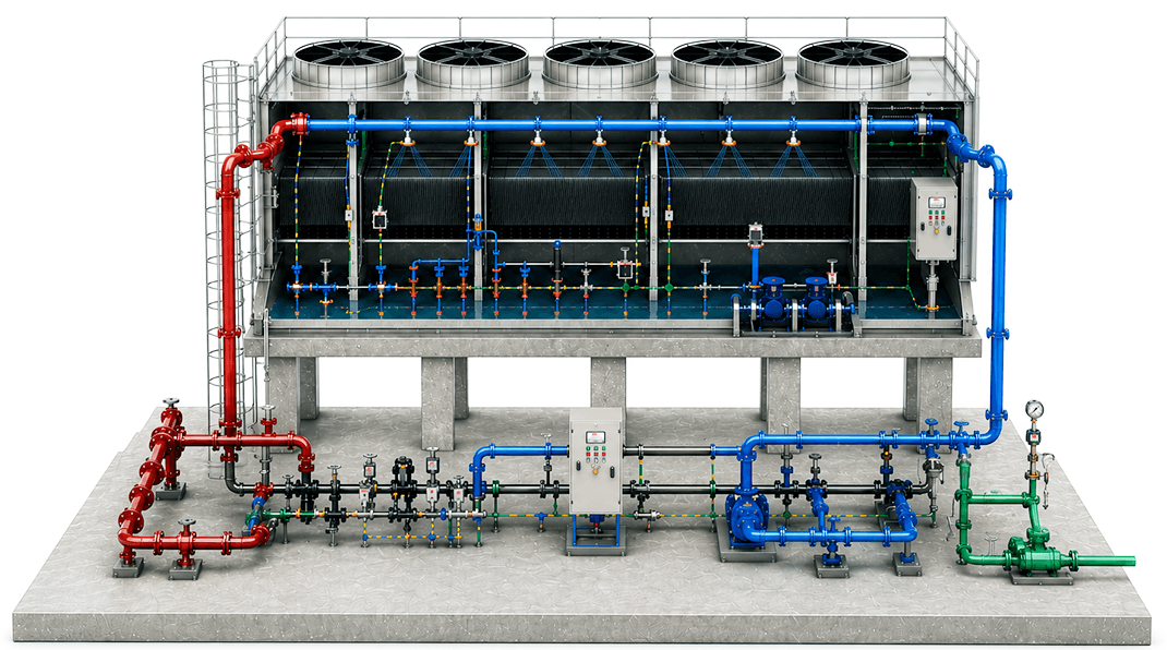
Conceptual application view. Not for installation design.
Cooling Tower Basics
Cooling towers remove heat by circulating water through moving air. As some water evaporates, makeup water must be added to maintain the proper basin level.
Ultrasonic level sensors monitor the basin level to help add makeup water and prevent pumps from running without sufficient water.
How Ultrasonic Level Sensors Work
Ultrasonic level sensors send sound pulses toward the water surface and measure the echo’s return time to determine the water level.
The sensor converts this measurement into a proportional 4-20 mA signal for automatic control of pumps, valves, or building-management systems.
Ultrasonic Level Sensors

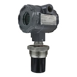


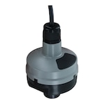
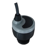
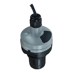
Information is provided for general reference only and does not replace official product documentation, professional advice, or applicable codes and standards.
Selecting a Ultrasonic Level Sensor for a Cooling Tower
Cooling towers are typically installed outdoors and exposed to weather, spray, condensation, and freezing conditions. Water falling through the tower can also create droplets, foam, or mist near the sensor. These conditions may interfere with the transmission or reception of an ultrasonic signal.
When selecting a sensor, consider the following:
- Choose an enclosure rated for the installation environment
- Select a sensor with sufficient range and signal strength for the basin
- Install the sensor above the highest expected water level
- Keep the sensor away from directly falling water whenever possible
- Ensure the sensor has a clear path to the water surface
- Avoid obstructions such as pipes, fittings, supports, and interior walls
Installation Options
There are two common installation methods for ultrasonic level sensors in cooling tower basins:
- A stand-pipe installation
- A side-mount bracket installation
Stand-Pipe Installation
A stand-pipe can improve measurement stability by reducing turbulence, isolating the sensor from falling water, and limiting the effects of surface foam.
The stand-pipe should be constructed as one continuous section of smooth pipe without breaks or internal transitions. Its inside diameter must be large enough to accommodate the sensor’s beam width; a larger diameter is generally preferable.
Recommended installation practices include:
- Use a low-profile, slip-by-thread coupling at the top of the pipe
- Drill two opposing ¼-inch vent holes just below the coupling and within the sensor’s deadband
- Extend the pipe to the bottom of the basin or below the lowest point in the measurement span
- Cut the bottom of the pipe at a 45-degree angle
- Maintain the basin level above the angled opening so the pipe remains filled with water
Side-Mount Bracket Installation
A side-mount bracket may be used when the sensor can be installed against the basin wall or on an aperture extending over the basin.
The mounting surface should be:
- Stable and accessible
- Flat and perpendicular to the water surface
- Located above the highest expected water level
- Positioned so the sensor has an unobstructed view across the full measurement span
Tank Adapters and Couplings
When a tank adapter is required, use a slip-by-thread adapter where the mounting surface is level. Avoid thread-by-thread adapters when possible, and do not install a tank adapter upside down.
For couplings, a short half-coupling is generally preferable to a taller full coupling. Use a slip-by-thread coupling and avoid thread-by-thread configurations.
The goal is to keep the sensor face as close as practical to the basin while maintaining a clear acoustic path and respecting the sensor’s deadband.
Electrical Considerations
Cooling towers often include large pumps, motors, and variable-frequency drives. These devices can generate electromagnetic or radio-frequency interference that may affect instrumentation.
For a reliable installation:
- Ground pumps, motors, drives, and associated equipment to earth
- Ground the ultrasonic sensor to the same earth ground
- Use proper wiring and shielding practices
- Consider surge protection in areas prone to lightning
- Use filtering or power conditioning where the electrical supply is unreliable
Configuring the Measurement Span
The ultrasonic sensor’s 4–20 mA output corresponds to the configured measurement span.
A typical configuration assigns:
- 4 mA to the empty or minimum measured level
- 20 mA to the full or maximum measured level
The low-level setpoint should leave enough water to protect the recirculation pump. The high-level setpoint should provide adequate operating capacity without allowing the basin to overflow.
DwyerOmega | Blog | What are Anemometers?
Written by: Dan Schultz
Published on: April 17, 2026