


A Wheatstone bridge is an electrical circuit used to precisely measure unknown electrical resistance or detect extremely small changes in resistance. Originally developed by Samuel Hunter Christie in 1833 and later refined and popularized by Sir Charles Wheatstone in 1843, the circuit is still relied on in electrical measurement and sensor technology.
A Wheatstone bridge operates by balancing two voltage-divider circuits. When the bridge is balanced, the output voltage is zero. Any change in resistance, such as that caused by mechanical strain, pressure, or temperature, creates an imbalance that produces a measurable output voltage proportional to the resistance change. This ability to detect minute variations with exceptional accuracy makes the Wheatstone bridge significantly more sensitive than a simple voltage divider for many precision measurement applications.
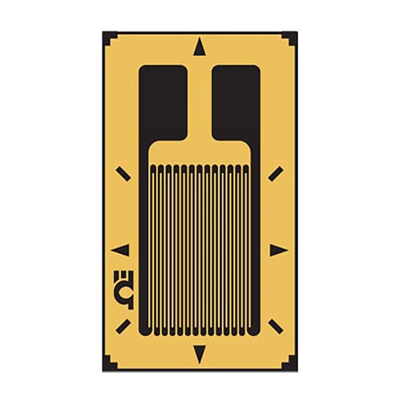
Today, Wheatstone bridges are widely used in instrumentation systems, particularly with bonded resistance strain gauges, load cells, pressure transducers, and other resistive sensors. By converting extremely small resistance changes into measurable electrical signals while helping minimize the effects of factors such as temperature variation, the Wheatstone bridge has become a foundational circuit in industrial measurement, product testing, structural monitoring, and process control.
Wheatstone Bridge Circuit Configuration
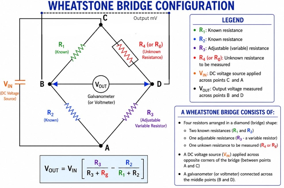
A Wheatstone bridge consists of four resistors connected in a diamond-shaped circuit. Two resistors (R1 and R2) have known resistance values, R3 is typically an adjustable resistor used to balance the bridge, and R4 (or Rg) is the unknown resistance or sensing element being measured.
A DC excitation voltage (VIN) is applied across opposite corners of the bridge (points A and C), creating two voltage-divider circuits. The output voltage is measured between the remaining two corners (B and D). Rather than measuring resistance directly, the Wheatstone bridge compares the voltages produced by these two voltage dividers. When both voltages are equal, the bridge is balanced and the output voltage is zero. Any change in the unknown resistance creates an imbalance, producing a measurable output voltage proportional to the resistance change.
How Do Wheatstone Bridges Work?
The accuracy of a Wheatstone bridge depends on whether the circuit is balanced or unbalanced. Understanding these two operating conditions is essential to understanding how the bridge detects and measures an unknown resistance.
A Wheatstone bridge is considered balanced when the ratio of resistances in one branch of the circuit is equal to the ratio of resistances in the opposite branch. Under this condition, the voltage at the two midpoint nodes is identical, resulting in no current flowing through the galvanometer (or other measuring device). Because there is no voltage difference across the output, the bridge is in equilibrium, allowing an unknown resistance to be calculated accurately using the bridge balance equation. This balanced condition is the foundation of the Wheatstone bridge's exceptional precision in resistance measurement.
| Balanced Bridge | Unbalanced Bridge |
|---|---|
| Resistance ratios are equal | Resistance ratios are not equal |
| Points B and D are at the same voltage | Points B and D are at different voltages |
| VOUT = 0 | VOUT ≠ 0 |
| No current flows through the measuring device | Current flows through the measuring device |
| Used to determine an unknown resistance | Used to detect and monitor resistance changes |
| Ideal for precision resistance measurements | Ideal for sensing and measurement applications |
Why Strain Gauges Use Wheatstone Bridge Circuits

A strain gauge is a sensor that measures mechanical deformation by converting strain, such as stretching or compression, into a change in electrical resistance. While this change in resistance is directly related to the amount of strain, it is extremely small. In many applications, resistance changes by only a fraction of an ohm, making it difficult to measure accurately using conventional methods. Wheatstone bridges are used to accurately measure these extremely small resistance changes.
Rather than measuring resistance directly, a Wheatstone bridge detects the small voltage imbalance created when a strain gauge changes resistance. When the strain gauge is incorporated into one or more arms of the bridge, any applied force, pressure, or deformation changes the gauge's resistance. This change unbalances the bridge, producing a small output voltage that is proportional to the amount of strain.
Wheatstone Bridge Configurations for Strain Gauges
The performance of a strain measurement system depends on how many strain gauges are incorporated into the Wheatstone bridge. The three most common configurations are quarter bridge, half bridge, and full bridge.
| Configuration | Active Strain Gauges | Sensitivity | Temperature Compensation | Typical Applications |
|---|---|---|---|---|
| Quarter Bridge | 1 | Good | Limited | Laboratory testing, basic strain measurements |
| Half Bridge | 2 | Better | Good | Structural testing, beam bending, fatigue testing |
| Full Bridge | 4 | Highest | Excellent | Load cells, pressure transducers, torque sensors, industrial force measurement |
Quarter Bridge Configuration
A quarter-bridge circuit uses one active strain gauge, while the remaining three bridge arms contain fixed precision resistors.
This is the simplest and most economical configuration, making it well suited for laboratory testing, experimental measurements, and applications where only a single strain location needs to be monitored. However, because only one bridge arm responds to strain, the output voltage is relatively small, and the circuit provides limited compensation for temperature-induced resistance changes.
Half-Bridge Configuration

A half-bridge circuit incorporates two active strain gauges within the bridge.
The gauges are typically arranged so that one experiences tension while the other experiences compression, or one acts as an active gauge while the other provides temperature compensation. Because both gauges contribute to the bridge output, the circuit produces a larger voltage signal than a quarter bridge while improving measurement accuracy and reducing the effects of temperature variation.
Full Bridge Configuration
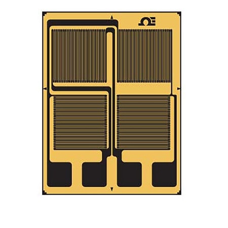
A full-bridge circuit uses four active strain gauges, with each bridge arm contributing to the measurement.
As strain is applied, two gauges increase in resistance while the other two decrease. These opposing resistance changes maximize the bridge output, producing the highest sensitivity of the three configurations. The symmetrical arrangement also provides excellent temperature compensation and minimizes errors caused by environmental influences.
For these reasons, full-bridge circuits are commonly used in load cells, pressure transducers, torque sensors, and other high-precision industrial instrumentation where measurement accuracy and long-term stability are critical.
Strategic Installation
Strain gauge circuits produce low-level voltage signals, often requiring sensitivities around 100 microvolts or better. This makes them particularly susceptible to noise from electrical devices. Potential error sources include capacitive coupling from lead wires running near AC power cables, magnetic induction from variable magnetic fields, parasitic contact resistances in lead wires, insulation failures, and thermoelectric effects at junctions of dissimilar metals. These interferences can significantly degrade signal quality.
Shielding
To mitigate electrical interference and noise, implementing proper shielding is crucial. Enclosing measurement lead wires within a shield intercepts external interferences and can reduce errors from insulation degradation. Shielding also protects against capacitive coupling. When measurement leads are routed near sources of electromagnetic interference, such as transformers, twisting the leads helps minimize signal degradation due to magnetic induction by canceling out induced currents. In industrial applications, twisted and shielded lead wires are commonly employed to maintain signal integrity.
Guarding
Beyond shielding, guarding the instrumentation itself is equally important. A guard, typically a sheet-metal enclosure surrounding the analog circuitry, is connected to the shield to ensure all components are at the same electrical potential, preventing extraneous current flows. Ground currents flowing through the strain gauge element or its lead wires can be indistinguishable from the measurement signal in a Wheatstone bridge circuit. Implementing guarding ensures that terminals of electrical components remain at the same potential, thereby preventing error-inducing currents. Additionally, connecting a guard lead between the test specimen and the negative terminal of the power supply provides an alternative path for error-producing currents, ensuring all elements involved are at the same potential as the test specimen.
Lead-Wire Effects
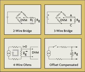
Strain gauges are sometimes mounted at a distance from the measuring equipment. This increases the possibility of errors due to temperature variations, lead desensitization, and lead-wire resistance changes. In a two-wire installation, the two leads are in series with the strain-gauge element, and any change in the lead-wire resistance (R1) will be indistinguishable from changes in the resistance of the strain gauge (Rg).
To correct for lead-wire effects, an additional, third lead can be introduced to the top arm of the bridge. In this configuration, wire C acts as a sense lead with no current flowing in it, and wires A and B are in opposite legs of the bridge. This is the minimum acceptable method of wiring strain gauges to a bridge to cancel at least part of the effect of extension wire errors. Theoretically, if the lead wires to the sensor have the same nominal resistance, the same temperature coefficient, and are maintained at the same temperature, full compensation is obtained. In reality, wires are manufactured to a tolerance of about 10%, and three-wire installation does not completely eliminate two-wire errors, but it does reduce them by an order of magnitude. If further improvement is desired, four-wire and offset-compensated installations should be considered.
In two-wire installations, the error introduced by lead-wire resistance is a function of the resistance ratio R1/Rg. The lead error is usually not significant if the lead-wire resistance (R1) is small in comparison to the gauge resistance (Rg), but if the lead-wire resistance exceeds 0.1% of the nominal gauge resistance, this source of error becomes significant. Therefore, in industrial applications, lead-wire lengths should be minimized or eliminated by locating the transmitter directly at the sensor.
Temperature and the Gauge Factor
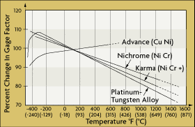
Strain-sensing materials, such as copper, change their internal structure at high temperatures. Temperature can alter not only the properties of a strain gauge element but also can alter the properties of the base material to which the strain gauge is attached. Differences in expansion coefficients between the gauge and base materials may cause dimensional changes in the sensor element. Therefore, a temperature compensation circuit would be needed.
DwyerOmega | Blog | What is a Pressure Gauge?
Written by: Dan Schultz
Updated on: October 30, 2025

DwyerOmega | Blog | What is an Intrinsically Safe Product?
Written by: Dan Schultz
Published on: March 30, 2026