Italia 800 906 907 | Internazionale +39 022 333 1521 | Benvenuti sul nostro nuovo sito web. Avete riscontrato un problema o un bug? Segnalatelo qui.



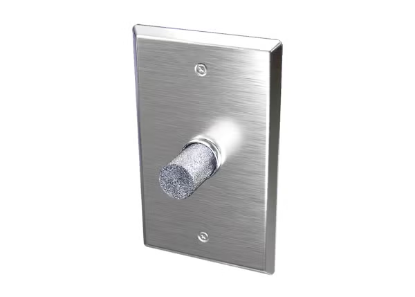
RH-Wall-Plate
Sensore da parete per umidità relativa
- Farmaceutico
- Ospedali
- Sala operatoria
- Vivai
- Controllo di processo
RH-Wall-Plate
Da


Panoramica del Prodotto
- Collegamento elettrico Terminale a vite
- Materiale della custodia Acciaio inossidabile
- Altezza 1.5 in
- Lunghezza 4.5 in
- Resistenza in ingresso Minimo 4K Ohm
- Corrente, max 8 mA
- Tipo di misurazione Umidità
- Temperatura di esercizio, max 60 °C
- Temperatura di esercizio minima -40 °C
- Dettagli sull'uscita 0-5 VCC: 12 - 40 VCC / 18 - 28 VCA
- Umidità relativa 10 al 95%
- Tipo di sensore di umidità relativa Capacitivo con filtro idrofobico
- Ripetibilit ± 0,05°C
- Tempo di risposta 1°C/secondo escluso il tempo di assestamento
- ID serie RH-Wall-Plate
- Temperatura di stoccaggio, max 65 °C
- Temperatura di stoccaggio, min. -40 °C
- Tipo di alimentazione CC
- Tensione di alimentazione 24 Vcc
- Peso 0.235 lb
- Larghezza 2.75 in
- Calibro del cavo Da 26 a 16 AWG
Supported Applications
The ACI A/RH Wall Plate Series is a Relative Humidity transmitter designed for use with electronic controllers in commercial heating and cooling building management systems. The series utilizes a thermoset polymer capacitive sensing element to deliver a proportional analog voltage output signal equivalent to 0 to 100% RH. Documented applications include pharmaceutical facilities, hospitals, operating rooms, vivariums, clean rooms, process control environments, wash-down areas, and stability chambers.
Operating Conditions & Performance
The transmitter operates within a relative humidity range of 0 to 95% RH (non-condensing) with conformally coated PCBs for protection against moisture and contaminants. The operating temperature range is -40 to 140 °F (-40 to 60 °C), while the storage temperature range extends from -40 to 149 °F (-40 to 65 °C). Accuracy at 77°F (25°C) is specified as +/- 2% or 3% from 10 to 95%. The series exhibits less than 2% drift over 5 years, with a repeatability of 0.5% RH and sensitivity of 0.1% RH.
Power requirements vary by output configuration: the 0-5 VDC signal requires 12 - 40 VDC or 18 - 28 VAC supply voltage, while the 0-10 VDC signal requires 18 - 40 VDC or 18 - 28 VAC. The unit features reverse polarity protection and draws a maximum of 8 mA VA (0.32 VA). A recommended stabilization time of 30 minutes is required before performing accuracy verification.
Configuration Options
The series offers configurable output signals, factory calibration options, and specific sensor configurations to meet diverse installation needs.
- Output Signal: Field-selectable via integral DIP switches for 0-5 VDC or 0-10 VDC (3-wire configuration). Default outputs are selectable at the time of order as either 0-5 VDC or 0-10 VDC.
- Accuracy Classes: Available in +/- 2% or +/- 3% accuracy from 10 to 95% RH.
- Housing & Materials: Features a single-gang wall mounting plate constructed of 430 Stainless Steel with a brushed finish. The sensor includes a hydrophobic filter and is protected by Cross-linked LPDE (White) foam rated FMVSS-302, along with a temporary plastic cover for wash-down applications.
- Calibration & Verification: Units include integral 0%, 50%, and 100% test options to verify operation. Field calibration is possible using increment/decrement DIP switches without replacing the sensing element. Three-point NIST Calibration Certificates are available as an option.
- Electrical Connections: Screw terminal blocks (polarity sensitive) accept wire sizes from 16 AWG (1.31 mm²) to 26 AWG (0.129 mm²). The minimum load resistance is 4K Ω, and the recommended torque rating for terminals is 4.43 to 5.31 lb-in (0.5 to 0.6 Nm).
- Approvals: CE, UKCA, RoHS, WEEE.
Key Product Differences
The series is distinguished by accuracy class and default output signal configuration in the model number construction (e.g., A/RH2-SP-05). The "RH2" designation indicates +/- 2% accuracy, while "RH3" denotes +/- 3% accuracy. Models ending in "-05" have a default 0-5 VDC output with selectable 0-10 VDC capability; models ending in "-010" feature a default 0-10 VDC output with selectable 0-5 VDC capability.
Specific variants include the standard transmitters and those equipped with NIST certificates (e.g., A/RH2-SP-05-NIST). The series does not support an optional temperature sensor in this specific wall plate configuration; that option is documented for other ACI families but not enumerated as a variant or feature of the RH-Wall-Plate data sheet.
PDF & Manuali