Need assistance? Call us: 1-800-663-4209



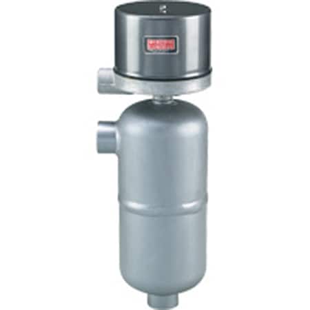
Series-251-253-254Configuration
Welded Chamber Liquid Level Control, 1250 psig, Hermetic Switches
- Welded-steel chamber rated 1250 psi @ 100 °F, 750 psi @ 750 °F for high-pressure / high-temp service
- Handles fluids to 0.60 SG with 1″ NPT or flanged side/bottom connections for easy mounting
- Stainless float with magnetic actuation offers smooth, reliable level switching
- SPST, SPDT, or DPDT switch options with general, weather, or explosion-proof enclosures


Product Overview
- Series ID Series-251-253-254
Supported Applications
The Dwyer Series 251, 253, and 254 are magnetic liquid level controls designed for the control of compatible liquids in high-pressure environments. These welded chamber external mount units feature hermetically sealed switches suitable for applications requiring operating pressures up to 1250 psig (86 bar) at temperatures reaching 750°F (400°C). The series utilizes a time-proven magnetic head leak-proof construction combined with heavy-duty welded chambers, employing an external magnet design that reduces the possibility of magnetic particle build-up inside the armature tube.
Operating Conditions & Performance
The Series 251-253-254 supports a process temperature range up to 750°F (400°C) and an ambient operating temperature of 212°F (100°C). Standard pressure ratings are 1250 psig (86 bar) at 100°F (38°C), decreasing to 750 psig (52 bar) at 750°F (400°C). The controls require a minimum liquid specific gravity of 0.75 for proper operation.
Performance characteristics include:
- Repeatability: ±1/4" (6.4 mm)
- Single Stage Level Change: For Specific Gravity 1.0, the level change is 7-1/4" (184 mm) with a differential of 3/4" (19 mm). For Specific Gravity 0.75, the level change is 8" (203 mm) with a differential of 1" (25.4 mm).
- Two Stage Level Change: Configurations vary by specific gravity and stage spacing; for example, at Sp Gr 1.0, dimensions include A: 6-1/4" (159 mm), B: 3/4" (19 mm), C: 8-1/2" (216 mm).
Configuration Options
The series offers extensive configuration options across housings, process connections, switch types, and materials to meet diverse installation requirements.
Housings and Enclosures
- G: General purpose, NEMA-1 (Painted steel and aluminum).
- WT: Weather proof, NEMA-3R, 4, 4X (Painted steel, aluminum, and neoprene).
- E: Explosion-proof, NEMA-7, 9; Class I Groups B, C, D; Class II Groups E, F, G (Aluminum).
- EV: Explosion-proof vapor proof, NEMA-7, 9; Class I Groups B, C, D; Class II Groups E, F, G (Aluminum and neoprene with 18" leads).
Process Connections and Construction
- Series 251: Combination 1" NPT/socket weld hubs; side/bottom mounting.
- Series 253: Flanged connections (side/bottom) available in 1" 150#, 300#, and 600# classes with corresponding pressure ratings of 275 psi, 720 psi, or 1250 psi at 100°F.
- Series 254: Flanged connections (side/side) available in 1" 150#, 300#, and 600# classes with corresponding pressure ratings of 275 psi, 720 psi, or 1250 psi at 100°F.
Switch Circuits and Materials
- Circuit Types: Mercury switches (SPST, SPDT, DP-ST) and Snap-action switches (SP-DT, DP-DT). High capacity DC snap switches and high temperature snap switches are available.
- Contact Options: Gold alloy contacts for low current service rated at 1 amp resistive or 0.5 amp inductive at 28 VDC (Circuit 7810 or 7806 only).
- Wetted Materials: C1 construction includes carbon steel, 303SS, 304SS, 316SS, and 430SS. Optional 316SS with 430SS is available.
Key Product Differences
The primary distinction between the series models lies in their process connection geometry and flange ratings:
- Type 251: Features welded carbon steel chambers with combination 1" NPT/socket weld hubs for side/bottom mounting.
- Type 253: Utilizes flanged connections mounted on the side and bottom, available in various pressure classes (C1-175, C1-375, C1-675).
- Type 254: Utilizes flanged connections mounted on both sides, available in matching pressure classes.
Switch configurations vary by circuit code. Mercury switches (Chart A) offer ratings such as 10 amps at 120V AC for SP-ST and DP-ST arrangements. Snap-action contacts (Chart B) provide ratings up to 12 amps at 120V AC for standard circuits, with hermetically sealed options rated at 5 amps. High temperature snap switches are available for continuous operation up to 800°F (425°C), though the Type 251-C1-75 is specifically noted as rated at 650 psi (45 bar) in this high-temp configuration.
Show Ratings & Reviews

