Need assistance? Call us: 1-800-663-4209



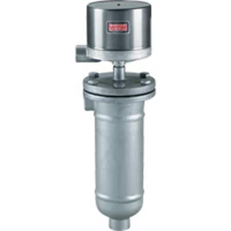
Series-211-213-214Configuration
Stainless Steel Float Level Switch, 1" NPT, 450 psi, Custom Circuits


Product Overview
- Series ID Series-211-213-214
Supported Applications
The Dwyer Series 211, 213, and 214 are magnetic liquid level controls designed for point-level detection in pressurized vessels. These external mount switches operate via mutual magnetic attraction between a plunger on the float and a magnet on the switch assembly, actuating when the float reaches the operating point and returning by gravity as the fluid drops.
Documented applications include liquid level control where minimum specific gravity is 0.60. The series supports service up to 450 psig (31 bar) at 100°F (38°C), with pressure ratings decreasing to 300 psig (21 bar) at process temperatures of 500°F (260°C). For high-temperature applications exceeding 350°F (177°C), the series offers options for heat fins.
Operating Conditions & Performance
The Series 211, 213, and 214 operate within a process temperature range up to 500°F (260°C) with an ambient operating limit of 212°F (100°C). Repeatability is specified as ±1/4" (6.4 mm).
Pressure ratings vary by model and flange class:
- Series 211: Standard 1" NPT connection rated at 450 psig (31 bar) at 100°F (38°C), reducing to 300 psig (21 bar) at 500°F (260°C).
- Series 213: Side/bottom flanged connections available in 1" 150#, 300#, and 600# classes. Ratings range from 275 psi to 450 psi at 100°F (38°C), with corresponding reductions at elevated temperatures.
- Series 214: Side/side flanged connections available in 1" 150#, 300#, and 600# classes, matching the pressure ratings of Series 213 for equivalent flange classes.
The series requires a minimum specific gravity of 0.60. Switch level changes vary by operation mode; single-stage operation at Sp Gr 1.0 shows a change (A) of 6-3/4" (171 mm), while two-stage configurations show different differential values depending on the pressure and temperature rating.
Configuration Options
The series offers extensive configuration options across enclosures, circuit arrangements, chamber construction, and special service features to meet diverse installation requirements.
Enclosure Ratings & Materials
- G (General Purpose): NEMA-1; painted steel and aluminum housing.
- WT (Weather Proof): NEMA-3R, 4, 4X; painted steel, aluminum, and neoprene.
- E (Explosion-proof): NEMA-7, 9 for Class I Groups B, C, D and Class II Groups E, F, G. Aluminum housing with optional breather/drain for high humidity or outdoor service.
- EV (Explosion-proof – Vapor-proof): NEMA-7, 9; aluminum and neoprene construction.
Circuit Arrangements & Switch Types
The series supports single-stage or two-stage operation with the following switch technologies:
- Mercury Contacts (Chart A): SPST, SPDT, DP-ST, and DP-DT configurations. Ratings include AC 120V/240V/440V at 10A/5A/3A and DC up to 250V.
- Snap Action Contacts (Chart B): SPDT, DP-DT options with ratings of 12A AC / 0.5A DC resistive or high capacity DC snap switches rated for specific amperage limits.
- Hermetically Sealed Snap Switches: Available as -7810HM and -7806HM variants with ratings of 5A at AC/DC voltages.
Chamber Construction & Connections
- Series 211: Flanged carbon steel chamber with standard side/bottom 1" NPT hubs. Socket weld hub (H2 option) available instead of NPT.
- Series 213: Side/bottom process connections using 1" RF forged steel flanges (ANSI specifications).
- Series 214: Two vertical side/side process connections using 1" RF forged steel flanges.
Materials & Approvals
The wetted materials include a carbon steel chamber with trim in 303SS, 304SS, and optional 430SS. The series carries UL and CSA approvals for the specified hazardous location groups.
Key Product Differences
Differences between Series 211, 213, and 214 are primarily defined by process connection geometry and flange class availability:
- Series 211: Features a standard 1" NPT pipe connection (side/bottom) or optional socket weld hub. It is the base model for external mount applications with carbon steel chambers.
- Series 213: Designed for flanged installations requiring side and bottom connections, available in ANSI Class 150#, 300#, and 600# ratings.
- Series 214: Configured with two vertical side/side flanges (ANSI specifications) to accommodate specific vessel orientations or piping layouts, also offered in Classes 150#, 300#, and 600#.
Circuit variations distinguish between mercury switch types (-48XX series), standard snap action switches (-78XX series), hermetically sealed variants (-HM suffix), high capacity DC switches (-98XX series requiring heat fins above 350°F/177°C), and high temperature snap switches rated to 800°F (425°C) continuous.
Show Ratings & Reviews

