Need assistance? Call us: 1-800-663-4209



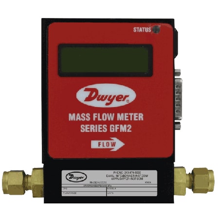
Series-GFM2Configuration
GFM2 Gas Mass Flow Meter, User-Selectable & Relay Outputs, Totalizer
- Straight-tube mass flow meter calibrated for up to 32 gases with user-selectable K-factors
- ±1% of full scale accuracy, ±0.25% repeatability-ideal for precision gas monitoring
- Analog 0-5 V or 4-20 mA output plus two programmable SPDT relays and totalizer
- RS-232/RS-485 digital interface, NIST-traceable calibration, and ≤1×10⁻⁹ cc He/s leak integrity


Product Overview
- Series ID Series-GFM2
Supported Applications
The Series GFM2 Gas Mass Flow Meter by Dwyer measures the mass flow rate of clean gases using a thermal dispersion principle with a straight tube sensor and restrictor flow element. The series is designed for applications requiring measurement across a wide variety of gases, including Air (AIR), Argon (AR), Acetylene (C2H2), Propane (C3H8), Butane (C4H10), Methane (CH4), Carbon Monoxide (CO), Carbon Dioxide (CO2), Hydrogen Fluoride (HF), Helium (HE), Hydrogen (H2), Nitrogen (N2), Ammonia (NH3), Oxygen (O2), and Sulfur Dioxide (SO2). The device stores calibration information for up to 10 different gases or user-specific K-factors.
Important operational constraints include a requirement that GFM2 transducers should not be used for monitoring OXYGEN gas unless specifically cleaned and prepared for such application. A warm-up period is required before accurate readings can be taken; the status LED emits a constant amber light during the first 6 minutes of initial powering, followed by a constant GREEN light indicating normal operation.
Operating Conditions & Performance
The Series GFM2 operates within a process temperature range of 32 to 122°F (0 to 50°C). The meter provides an accuracy of ±1% FS and repeatability of ±0.25% FS, with a response time of 2 seconds to within ±2% of actual flow. Maximum pressure in the gas line should not exceed 500 PSIA (34.47 bars), consistent with the rated pressure limit of 500 psig (34.5 bar).
Flow measurement ranges vary by body size and specific gas, spanning from low-flow configurations up to high-flow capacities. The series supports flow rates as documented in the specification tables: Body Size 010 covers ranges such as 10 mL/min for Air; Body Size 050 extends to higher flows like 50 L/min for Air; and Body Size 100 accommodates up to 100 L/min for Air. Maximum pressure drops are specified per model, with the GFM2-X-101 listing a maximum of 130 mm H2O (0.18 psid / 1.275 kPa).
Configuration Options
The Series GFM2 is configurable across multiple dimensions to meet specific installation and measurement needs.
- Housing & Materials: Body sizes include Low Flow (010), Medium Flow (050), and High Flow (100). Housing materials are available as Aluminum for Body Size 010, or Stainless Steel for all body sizes. Wetted parts configurations vary by model: GFM2-X-X-A features anodized aluminum, brass, 316 SS with fluoroelastomer O-rings; GFM2-X-X-S utilizes 316 SS and fluoroelastomer O-rings, with Buna-N, EPR, and PTFE O-rings optional.
- Process Connections: Fittings are selected based on flow rate: 1/8" compression for ≤ 10 L/min; 1/4" for ≤ 50 L/min; and 3/8" for ≤ 100 L/min. Model codes A, B, and D correspond to these fitting sizes.
- Outputs & Signals: Analog outputs include Linear 0 to 5 VDC (minimum load impedance 3000 Ω) or 4 to 20 mA (maximum loop resistance 500 Ω). All 4-20 mA current loop outputs are self-powered and non-isolated. The series includes two electromechanical SPDT relays with latch options for high/low gas flow alarms.
- Display & Communication: An optional local 2x16 LCD readout is available (code L) or no display (code N). Digital interfaces include RS-232, RS-485 (supporting multi-drop capability of up to 256 units), and Profibus DP. The device supports programming via support software.
- Engineering Units: Flow can be displayed in 23 different engineering units including % FS, mL/sec/min/hr, L/sec/min/hr, m³/sec/min/hr, ft³/sec/min/hr, g/sec/min/hr, kg/sec/min/hr, and Lb/sec/min/hr. A user-defined unit option is also available.
Key Product Differences
The Series GFM2 model number structure defines specific configurations: GFM2 - [Specialty Gas & K-Factor] - [Body Size] - [Body Material] - [Seal Material] - [Fittings] - [Display] - [Output Signal] - [Digital Interface]. For example, a unit configured as GFM2-AIR-010-A-V-N-A-2 indicates Air calibration, Low Flow body size (010), Aluminum housing (A), Fluoroelastomer seals (V), 1/8" compression fittings (N in the fitting position corresponds to code A for low flow per table mapping logic, though model guide example uses N for No Display; specific codes map as: Fittings A=1/8", B=1/4", D=3/8"); Output Signal A is 0-5 VDC; and Digital Interface 2 is RS232.
Physical dimensions with process connection fittings attached are listed as 1-1/8 [28.70] x 3-5/32 [80.16] x 4-29/64 [112.97]. The transmitter weight is documented in the manual table as 2.20 lb (1.00 kg) for shipping, while extracted scalar data lists a unit weight of 1.05 lb (0.48 kg). Power supply requirements are 11 to 26 VDC; applying voltage above 26 VDC is prohibited.
PDFs & Manuals
Show Ratings & Reviews
we have your mass flow transmitter. We need to watch value from this transmitter to our computer. we cannot using 4-20 mA signal because we have not any plc. But we can use rs485 to usb converter and we can read any register. Can you share any manual?
Hello,
See the link below for the manual.
https://assets.dwyeromega.com/manuals-do/GFM2_44405200__XFM__Rev_A.pdf
Date published: 2026-02-03

