Need assistance? Call us: 1-800-663-4209



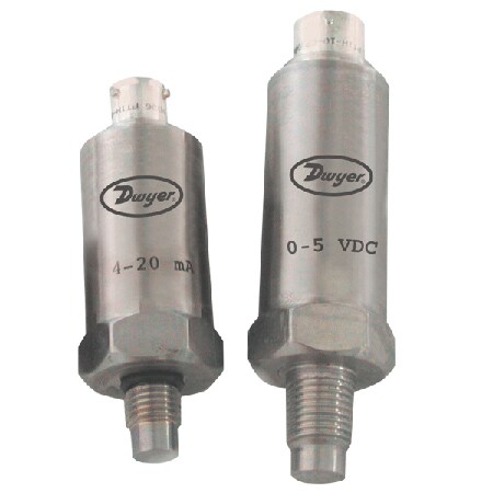
Series-FDTConfiguration
Flush Diaphragm Transmitter for Cyclical Conditions - OEM & Process Use


Product Overview
- Series ID Series-FDT
Supported Applications
The Dwyer Series FDT Flush Diaphragm Transmitter is engineered for highly cyclical conditions where standard sensors may fail. The flush sensor feature prevents inaccuracies caused by build-up or blockage, making the series suitable for compatible liquids and gases, adhesives, slurries, materials that can harden, or applications where a pressure cavity is not desired.
The solid steel sensing diaphragm withstands abrasive environments and high cyclical conditions involving water-hammering or spiking. The flush design significantly reduces the chance of leakage in these harsh process conditions.
Operating Conditions & Performance
The Series FDT operates within a temperature range of -40 to 200°F (-40 to 93°C), with compensated performance specified from 0 to 170°F (-18 to 77°C). The unit maintains an accuracy of ±0.5% FS (includes non-stability, hysteresis, and repeatability) across its measurement ranges.
Key performance specifications include:
- Response Time: <1 ms
- Stability: ±0.25% FS per year
- Thermal Effect: ±1.5% FSO over compensated range
- Pressure Limits: 150% FS proof pressure; 200% FS burst pressure
- Enclosure Rating: NEMA 4X (IP66)
The transmitter is designed to mount in any position and weighs 2 oz (57 g).
Voltage & Load Requirements
- Power Supply: 8-38 VDC. The device is not designed for 120 or 240 volt AC operation.
- FDT-A (Current Output): Loop resistance of 0 to 1.5 Ω.
- FDT-V (Voltage Output): Load resistance ≤ 100 Ω.
Configuration Options
The Series FDT is available in two primary output configurations: the FDT-A model providing a 4-20 mADC signal and the FDT-V model delivering a 0-5 VDC (3-wire) output. The series supports multiple pressure ranges, including 100 psi, 150 psi, 200 psi, 300 psi, 500 psi, 1000 psi, 2000 psi, and 5000 psi.
Process Connections & Materials
- Standard Connection: 7/16-20 UNF male flush diaphragm.
- Optional Connection: 1/4" male NPT.
- Wetted Materials: Pressure cavities are manufactured with 316 and 15-5 stainless steels (SST).
Electrical & Accessories
- Connector Type: Bendix 4-pin connector.
- Mating Connector Option: A-168 for 4 pin M-12.
- Calibration Option: NISTCAL-PT1 provides a NIST traceable calibration certificate.
Key Product Differences
The Series FDT distinguishes between current and voltage output models, which differ in physical dimensions. The 0-5 VDC model (FDT-V) has an overall length of 3.25" with a 1.00" diameter, while the 4-20 mA model (FDT-A) measures 2.50" in overall length with the same 1.00" diameter and flange thickness.
Both models share identical mounting depth specifications of 0.525" and a flange thickness of 0.400". The series is not field repairable; units requiring service must be returned to the manufacturer with a return goods authorization number.
PDFs & Manuals
Show Ratings & Reviews

