Need assistance? Call us: 1-800-663-4209



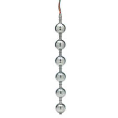
Series-F7-MSConfiguration
Multi-Station Level Switches for Water, Oil, Diesel – 6 Control Points


Product Overview
- Series ID Series-F7-MS
Supported Applications
The Dwyer Series F7-MS Multi-Station Level Switches are designed for vertical installation in tank tops (mounting up) or tank bottoms (mounting down). These switches operate normally with inclinations up to ±30° and provide customized level control points, supporting configurations of 1 to 6 switch locations. The series is engineered for use with compatible liquids including water, oil, and diesel.
Operating Conditions & Performance
The Series F7-MS accommodates specific process temperature ranges based on the selected float material. Buna-N floats support temperatures up to 180°F (82.2°C) in water and -40°F to +230°F (-40°C to +110°C) in oil. Stainless steel floats extend this range to -40°F to +300°F (-40°C to +148.9°C). Pressure ratings vary by mounting type, float material, and unit length: 150 psi for Mounting Types 1, 2, and 3 with Buna-N; up to 750 psi for these types with 316 SS floats (units <72"); and reduced limits of 300 psi for units >72". Mounting Type 4 supports 150 psi or 750 psi depending on float material, while Mounting Type 5 ranges from 100 psi to 750 psi based on housing and stem materials.
Media compatibility requires a minimum specific gravity of .75 for Buna-N floats (or .55 for certain types) and .75 for 316 SS floats. Actuation levels are calibrated on descending fluid level with water, featuring a tolerance of ±1/8". The switches offer excellent repeatability and are designed to resist shock and vibration.
Configuration Options
The series offers extensive configuration options across mounting types, materials, switch configurations, and integrated sensing capabilities:
- Mounting Types & Connections: Available in five styles: Type 1 (1/2" NPT), Type 2 (1-1/4" NPT), Type 3 (2" NPT), Type 4 (3" 150# Flange, Carbon Steel or 316 SS), and Type 5 External Mount (2-5/8" FNPT). Maximum overall lengths range from 36" for Type 1 to 140" for Types 3 and 4.
- Materials: Stems, connections, and floats are available in Brass or 316 Stainless Steel. Float stops include Beryllium Copper Grip Rings (Brass units) or S.S. ARMCO PH-15-7MD Grip Rings (Stainless Steel units). Units greater than 72" overall length utilize collars with setscrews instead of float-stop rings.
- Switch Configurations: SPST and SPDT options are available. Electrical ratings include SPST at .17 A @ 120 VAC, .08 A @ 240 VAC, .13 A @ 120 VDC, or .06 A @ 240 VDC; SPDT rated for .8 A @ 120 VAC and .4 A @ 240 VAC.
- Integrated Temperature Sensors: Optional thermistors provide continuous indication (10,000 ohms @ 77°F/25°C) with a tolerance of ±0.2°C from 32°F to 158°F (0°C to 70°C). Thermostats are available for switch action settings between 150°F and 175°F.
- Electrical Connections: Lead wires include #24 AWG free leads, #22 AWG TFE jacketed, or #18 AWG polymeric. A NEMA 4 junction box is available as an option (not compatible with connection type 1).
Key Product Differences
The Series F7-MS distinguishes itself through configurable set points and material pairings tailored to specific pressure and temperature requirements. Model numbers explicitly define the number of switch points, stem length (L0), individual actuation distances (L1–L6 referenced from the bottom of the process connection), float type (F1, F2, or F3), and construction materials.
Key variations include:
- Float Types: Buna-N floats are offered in two specific gravity ratings (.75 s.g. for 150 psi; .55 s.g. for Type 1, 3, 4, 5 at 150 psi). Stainless steel floats support higher pressures (up to 750 psi) and temperatures up to +300°F.
- Mounting Orientation: While designed primarily for vertical installation, the series supports inclinations of ±30° from vertical.
- Switch Logic: Normally Open (NO) is standard; Normally Closed (NC) configurations are indicated by an asterisk (*) in the model number following the set point distance.
PDFs & Manuals
Show Ratings & Reviews


Stem & Connection Material
Connection Type
Number of Switch Points
Float Type
Switch Type
Set Point Distance (L6)
Set Point Distance (L5)
Set Point Distance (L4)
Set Point Distance (L3)
Set Point Distance (L2)
Set Point Distance (L1)
Overall Length (LO)
Options
NO (normally open) switch is standard. For NC (normally closed), place an asterisk (*) after the corresponding set point distance value.
Maximum overall length by Connection Type: Type 1 = 36 In (91.4 cm); Type 2 = 60 In (152.4 cm); Types 3, 4 or 5 = 140 In (355.6 cm). Minimum length is L1 + D.