Need assistance? Call us: 1-800-663-4209



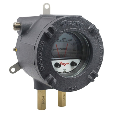
Series-AT-3000MR-MRSConfiguration
ATEX/IECEx Photohelic® Switch/Gage for Differential Pressure Measurement
- Gage reading unaffected by switch operation and will continue to read pressure even during power loss
- Zero and range adjustments outside of gage means no disassembly in normal service
- Solid-state design allows for switching in high cycle rate applications without degradation
- Flameproof enclosure with optional glass window and aluminum housing protects the device in hazardous areas while giving local visibility to process pressure and set point status
- Increased response time at low pressures with LD port configuration


Product Overview
- Media Compatibility Clean dry air / inert gas, HVAC / room air, Inert / non-reactive gases
- Series ID Series-AT-3000MR-MRS
Supported Applications
The Dwyer Series AT-3000MR/MRS ATEX/IECEx Photohelic® Switch/Gage combines a precise differential pressure switch with an analog gage in a flameproof enclosure. Designed for hazardous areas, the series is intended for use with air and non-combustible, compatible gases as well as non-corrosive gases.
Operating Conditions & Performance
The Series AT-3000MR/MRS operates within an ambient temperature range of 20 to 120°F (-6.67 to 48.9°C). An optional low-temperature configuration (LT) extends the lower limit to -20°F (-28.8°C). Accuracy is specified as ±2% of full scale at 70°F (21.1°C), with specific model variations offering ±3% on -60PA models and ±4% on -00 models.
Measurement ranges span from low differential pressures up to higher limits, including:
- 0 to 0.25 w.c., 0 to 0.5 w.c., 0 to 1.0 w.c., and 0 to 2.0 w.c.
- 0 to 60 w.c., 0 to 125 w.c., 0 to 250 w.c., and 0 to 500 w.c.
The unit features an IP66 enclosure rating (IP65 for versions VS1, VS2, and VL1). Response time may increase at low pressures when using the LD port configuration. The device is designed with a diaphragm in a vertical mounting orientation; other orientations require factory consultation.
Approvals & Certifications
The series holds ATEX Certificate INERIS 21ATEX0033X and IECEx Certificate IECEx INE 21.0064X. Compliance ratings include:
- ATEX: Ⅱ 2G Ex db IIC T5, T6 Gb (-60°C≤Tas+50°C for T6; -60°C≤Tas+60°C for T5) and Ⅱ 2D Ex tb IIIC T75°C Db.
- IECEx: Ex db IIC T5, T6 Gb (-60°C≤Tas+50°C for T6; -60°C≤Tas+60°C for T5) and Ex tb IIIC T75°C Db.
Configuration Options
The series offers configurable options across enclosures, relay types, power supplies, port configurations, and temperature ranges. The housing material is aluminum with dimensions of 6-3/16" (157 mm) width, 7-1/64" (182 mm) height, and 8-23/64" (212.5 mm) depth.
Relay & Output Options
The series supports two primary output technologies:
- MRI Models: Electromechanical relays with SPDT (Single Pole Double Throw) configuration, featuring gold over clad silver contacts suitable for dry circuits.
- MRS Models: Solid state relay outputs utilizing solid-state technology for high repeatability and fast response.
Housing & Mounting Configurations
The enclosure is available with a blind cover or an optional glass window (W) for local visibility. Set points are adjustable via external knobs on the gage face. Electrical connections utilize screw terminals, and cable glands are not included.
Port & Valve Materials/Configurations
The process connection is 1/8" NPT female brass (stainless steel optional). Port configurations include:
- VSO/VL0: Standard or Low Differential port with no valve.
- VS1/VL1: Standard/Low Differential port with standard/low differential valve.
- VS2: Standard port with low differential valve.
Pressure limits vary by configuration; for example, the VS0 and VL0 configurations support 10 kPa when one or both pressure ports are connected. The VS1/VL1 supports up to 20 kPa (one port) or 15 kPa (both ports), while VS2 supports up to 40 kPa (one port).
Power & Environmental Options
The series accepts power supplies of 24 VDC, regulated ±10%, and is also available with a 24 VAC option. The standard temperature range covers -6.67 to 48.9°C (20 to 120°F), while the LT option extends operation down to -28.8°C (-20°F). A silicone-free construction (XSF) is available as an accessory.
Key Product Differences
The Series AT-3000MR/MRS distinguishes between electromechanical and solid-state relay technologies via the model suffix: "MR" denotes models with 1 Form C relays (SPDT), while "MRS" indicates units equipped with solid state relays. The series also differentiates by enclosure cover type, offering either a blind cover or a glass window for visual monitoring of the gage face.
Model numbering follows the structure: AT - [Enclosure] - [Model] - [Range] - [Relay Type] - [Power] - [Options] - [Cover] - [Port/Valve Config] - [Cable Entry]. For example, a model may be designated as AT-102NA-3000MR-0-24VDC-X-W1VS012. The "LT" option code specifically identifies units configured for low-temperature service down to -28.8°C (-20°F).
Accessories
Static Pressure Sensors for Manometers & Gages across Air Filters
From $2.55
0 In Stock
Industrial Control: Pressure Gauges, Flow Meters & Temp Controllers
From $4.00
0 In Stock
Show Ratings & Reviews
-
 70146900_dwg_dwg
-
 70146900_pdf_pdf
-
70146901_dwg_dwg
-
70146901_pdf_pdf
-
70146910_dwg_dwg
-
70146910_pdf_pdf
-
70146911_dwg_dwg
-
70146911_pdf_pdf
-
70146920_dwg_dwg
-
70146920_pdf_pdf
-
70146921_dwg_dwg
-
70146921_pdf_pdf
-
70146930_dwg_dwg
-
70146930_pdf_pdf
-
70146931_dwg_dwg
-
70146931_pdf_pdf
-
70146940_dwg_dwg
-
70146940_pdf_pdf
-
70146941_dwg_dwg
-
70146941_pdf_pdf