Skip to search Skip to main content Skip to navigation

Need assistance? Call us: 1-800-663-4209

We noticed you are in , please visit your local site by clicking the below link for regional offers and support.

Series-221-223-224Configuration

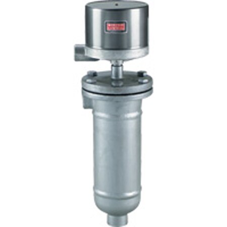
Flanged Chamber w/ Removable Float, 1" NPT, 1000 psi, Customizable

Series-221-223-224

Build your Part Number

Flanged Chamber w/ Removable Float, 1" NPT, 1000 psi, Customizable Series-221-223-224 Series-221-223-224
loading all models
Product Overview
  • Series ID Series-221-223-224

Supported Applications

The Dwyer Series 221, 223, and 224 are magnetic liquid level controls designed for heavy-duty industrial environments. These flanged chamber switches feature a removable float to facilitate inspection and maintenance without removing the entire assembly from service. Documented applications include oil refineries, chemical plants, power generating stations, pumping stations, heat transfer systems, sanitary/waste water facilities, drip legs, hydraulic systems, and boilers.

Operating Conditions & Performance

The series operates via mutual magnetic attraction between a plunger on the float and a magnet on the switch assembly. The switch actuates when the float reaches the operating point and returns to its original position by gravity as the level drops. Repeatability is specified at ±1/4" (6.4 mm).

Performance ratings vary by construction code, specific gravity, and temperature:

  • C1-60 Construction: Rated for 600 psig (41 bar) at 100°F (38°C), reducing to 550 psig (38 bar) at 475°F (246°C). Requires a minimum specific gravity of 0.6.
  • C1-75 Construction: Rated for 1000 psig (69 bar) at 100°F (38°C), reducing to 850 psig (59 bar) at 475°F (246°C). Requires a minimum specific gravity of 0.75.

Process temperature ranges up to 475°F (246°C). Ambient operating temperature is rated to 212°F (100°C).

Variations by Series and Connection Type

  • Series 221: Features a flanged carbon steel chamber with standard 1" NPT pipe weld connections. Optional configurations include 1" socket weld hubs or flanges.
  • Series 223: Utilizes 1" RF forged steel ANSI specifications for process connections, available in side/bottom or side/side orientations. Flange centerline is 14" (356 mm).
  • Series 224: Similar to Series 223 with 1" RF forged steel ANSI flanges but features a longer flange centerline of 14½" (371 mm). Available in side/side process connection configurations.

Configuration Options

The series offers extensive configurability across enclosures, circuit arrangements, and special service options to meet diverse installation requirements.

Enclosure Ratings and Materials

  • G (General Purpose): NEMA-1. Housing materials include painted steel and aluminum.
  • WT (Weatherproof): NEMA-3R, 4, 4X. Constructed from painted steel, aluminum, and neoprene.
  • E (Explosion-proof): NEMA-7, 9; Class I Groups B, C, D; Class II Groups E, F, G. Aluminum housing. CSA approved for Groups C, D, E, F, G only.
  • EV (Explosion-proof – Vapor-proof): NEMA-7, 9; Class I Groups B, C, D; Class II Groups E, F, G. Housing includes aluminum and neoprene. CSA approved for Groups C, D, E, F, G only.

Electrical connections vary by enclosure: terminal blocks are provided for G, WT, or E enclosures, while EV enclosures include 18" (460 mm) leads.

Circuit Arrangements and Switch Types

  • Mercury Switches: Available in single-stage SPST configurations that close as level falls or rises, SP-DT arrangements where one circuit closes as the other opens, and DP-ST/DP-DT two-switch options.
  • Snap-Acting Switches: Offered in single-stage (SPDT) and two-stage (2 SP-DT) configurations. Includes hermetically sealed snap switches (-7810HM/-7806HM).
  • High Capacity DC Snap Switches: Single stage (-98XX series) and two stage options available.
  • High Temperature Snap Switches: Continuous rating of 800°F (425°C). Note: For C1-60 types, pressure is rated at 350 psig (25 bar); for C1-75 types, pressure is rated at 550 psig (38 bar).

Options and Accessories

  • HF: High temperature fins. Recommended if ambient temperatures are extremely high or process temperatures exceed 500°F (260°C) for extended periods.
  • H2: Provides a 1" socket weld hub instead of the standard 1" NPT connection, and includes a breather and drain for E type enclosures. Recommended for high humidity or outdoor service.

Wetted Materials

The chamber is constructed from carbon steel. Trim materials include 316SS, 303SS, 304SS, and 430SS stainless steels.

Key Product Differences

Differences between the Series 221, 223, and 224 are primarily defined by their process connection geometry and flange specifications. The Series 221 is distinguished by its standard 1" NPT pipe weld interface with optional socket weld or flanged upgrades. In contrast, Series 223 and 224 are factory-configured with 1" RF forged steel ANSI flanges; the primary dimensional distinction between these two series is the flange centerline measurement (14" for Series 223 versus 14½" for Series 224). All three series share identical pressure/temperature rating envelopes based on their C1-60 or C1-75 construction codes and specific gravity requirements.

Weight varies by model: Series 221 weighs approximately 60 lb (27 kg), Series 223 is 70 lb (32 kg), and Series 224 is 77 lb (35 kg).

  • bvseo_sdk, java_sdk, bvseo-4.0.0
  • CLOUD, getReviews, 6ms
  • REVIEWS, PRODUCT
  • bvseo-msg: The resource to the URL or file is currently unavailable.;
  • bvseo_sdk, java_sdk, bvseo-4.0.0
  • CLOUD, getContent, 20ms
  • QUESTIONS, PRODUCT
  • bvseo-msg: The resource to the URL or file is currently unavailable.;
EXAMPLE 221 WT 7810 C1 60   221-WT-7810-C1-60 Liquid Level Control, weatherproof enclosure, SPDT snap switch, fixed deadband, automatic reset, operating pressure 600 psig (41 bar) at 100°F (38°C), 550 psig (38 bar) at 475°F (246°C), side/bottom process connections, 1" NPT, minimum specific gravity 0.60.
CONNECTION 221           One Vertical and One Horizontal 1" NPT
223           One Vertical and One Horizontal Flanged Connection
224           Two Vertical Flanged Connections
224T            
ENCLOSURE    G         General Purpose, NEMA 1
  WT         Weatherproof, NEMA 3R, 4, 4X
  E         Explosion-proof, NEMA 7, 9, Class I Groups B, C, D, Class II Groups E, F, G. CSA approved Groups C, D, E, F, G only.
  EV         Explosion-proof/Vapor-proof, NEMA 7, 9, Class I Groups B, C, D, Class II Groups E, F, G. CSA approved Groups C, D, E, F, G only.
CIRCUITS
(for electrical circuits
see charts A & B below)
    48XX       Single Stage Mercury Switch, see chart A
    48XX-XX       Two Stage, Mercury Switch, see chart A
    78XX       Single Stage, Snap Switch, see chart B
    78XX-XX       Two Stage, Snap Switch, see chart B
    78XXHM       Hermetically Sealed Snap Switch, see chart B
    98XX       Single Stage, High Capacity DC Snap Switch, use heat fins (HF) if process temperature exceeds 350°F (177°C), do not exceed 450°F (232°C), see chart B
    98XX-XX       Two Stage, High Capacity DC Snap Switch, use heat fins (HF) if process temperature exceeds 350°F (177°C), do not exceed 450°F (232°C), see chart B
    10XX       Single Stage, High Temp. Snap Switch, continuous rating 800°F (425°C), see chart B
    10XX-XX       Two Stage, High Temp. Snap Switch, continuous rating 800°F (425°C), see chart B
CHAMBER MATERIAL       C1     Carbon Steel Body
      C216     316SS Body
      HFC1     Heat Fins & Carbon Steel Body
SPECIFIC
GRAVITY
        60   0.60 Specific Gravity (221 only)
        75   0.75 Specific Gravity (221 only)
        160   0.60 Specific Gravity & 150# Flange (223, 224 only)
        175   0.75 Specific Gravity & 150# Flange (223, 224 only)
        360   0.60 Specific Gravity & 300# Flange (223, 224 only)
        375   0.75 Specific Gravity & 300# Flange (223, 224 only)
        660   0.60 Specific Gravity & 600# Flange (223, 224 only)
        675   0.75 Specific Gravity & 600# Flange (223, 224 only)
OPTIONS           H2 H2 Socket Weld Hub (221, steel housing only)
          STW SS Tag Wired
          01 Breather Only (E-Housing only)
          02 Drain Only (E-Housing only)
          12 Breather & Drain (E-Housing Only)
          23720 Fungus Proofing

CHARTS A & B - ELECTRICAL CIRCUITS AND RATINGS

SWITCH TYPE
SWITCH ACTION
ELECTRICAL RATINGS IN AMPS
ORDERING CODE
AC
DC
SINGLE STAGE
TWO STAGE
120V
240V
440V
30V
125V
250V
LOWER
UPPER
CHART A
Mercury Contacts
SP-ST open on level FALL
10
5
3†
 
10
5
-4821
-4821
-21
SP-ST open on level RISE
10
5
3†
 
10
5
-4820
-4820
-20
SP-DT one switch
4
2
1†
 
4
2
-4810
-4810
-10
SP-DT two switches E.I.*
10
5
3†
 
10
5
-4815
-4815
-15
DP-ST two switches E.I.* open on level FALL
10
5
3†
 
10
5
-4813
-4813
-13
DP-ST two switches E.I.* open on level RISE
10
5
3†
 
10
5
-4814
-4814
-14
DP-DT two SP-DT switches
4
2
1†
 
4
2
-4806
-4806
-06
CHART B
snap action contacts
SP-DT one switch
12
5
3†
 
0.5**
0.25**
-7810
-7810
-10
DP-DT two SP-DT switches
12
5
3†
 
0.5**
0.25**
-7806
-7806
-06
SP-DT one hermetically sealed switch
5
5
 
5**
 
 
-7810HM
-7810HM
-10HM
DP-DT two hermetically sealed SP-DT switches
5
5
 
5**
 
 
-7806HM
-7806HM
-06HM
DP-DT two SP-DT switches
10
3
 
 
10‡
3‡
-9806
-9806
-06
SP-DT one switch
10
3
 
 
10‡
3‡
-9810
-9810
-10
DP-DT Two SP-DT switches
2
2
 
 
0.4**
0.25**
-1006
-1006
-06
SP-DT one switch
2
2
 
 
0.4**
0.25**
-1010
-1010
-10
†Available on special order, change 1st digit in ordering code from 4 to 5 or 7 to 8, i.e., -4820 becomes -5820, -7810 becomes -8810, etc.
‡10 amp inductive (polarized) at 125 VDC.
*Electrically Independent.
**Resistive.

CHART C - MOUNTING STYLE

SERIES
MOUNTING
STYLE
MINIMUM
SPECIFIC
GRAVITY
PRESSURE RATING @
FLANGE
CLASS
psi)
ORDER
CODE
100°F
38°C
475°F
246°C
221
1" NPT
0.6
600 psi
41 bar)
550 psi
38 bar)
--
C1-60
221
1" NPT
0.75
1000 psi
69 bar)
850 psi
(59 bar)
--
C1-75
223
224
Flanged
0.6
275 psi
(19 bar)
150 psi
(10 bar)
150
C1-060
223
224
Flanged
0.6
600 psi
(41 bar)
550 psi
(38 bar)
300
C1-360
223
224
Flanged
0.6
600 psi
(41 bar)
550 psi
(38 bar)
600
C1-660
223
224
Flanged
0.75
275 psi
(19 bar)
150 psi
(10 bar)
150
C1-075
223
224
Flanged
0.75
720 psi
(50 bar)
625 psi
(43 bar)
300
C1-375
223
224
Flanged
0.75
1000 psi
(69 bar)
850 psi
(59 bar)
600
C1-675
en-US
en
Save Configuration