Need assistance? Call us: 1-800-663-4209



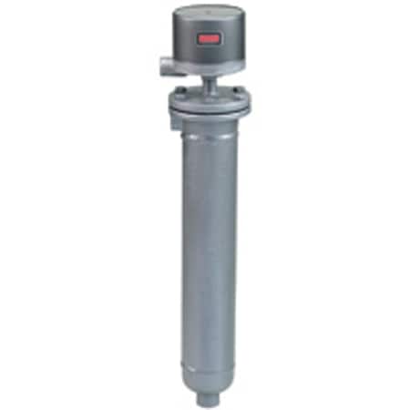
Series-215-217-218Configuration
Flanged Adjustable Deadband Controller for Refineries & Plants


Product Overview
- Series ID Series-215-217-218
Supported Applications
The Dwyer Series 215, 217, and 218 are flanged chamber adjustable deadband liquid level controls designed for heavy-duty industrial environments. These units incorporate magnetically actuated switch mechanisms operated by a magnetic armature placed into or out of the magnetic field of the switch magnet via float action. The series is suitable for oil refineries, chemical plants, and power stations where precise pump operation, high/low alarms, or shutdown sequences are required.
Applications include single-stage control with adjustable deadband for pump operation, as well as two-stage configurations combining an operating circuit (adjustable or fixed) with a separate alarm or trip circuit. The controls feature gravity return switch mechanisms activated by stainless steel floats within sealed chambers.
Operating Conditions & Performance
The series is engineered for process temperatures up to 500°F (260°C), with an ambient operating temperature of 212°F (100°C). Minimum specific gravity requirements are 0.60 for Types 215, 217, and 218.
Pressure ratings vary by type and flange class:
- Type 215: 450 psi (31 bar) at 100°F (38°C); 300 psi (21 bar) at 500°F (260°C).
- Type 217: 275 psi (19 bar) at 100°F; 150 psi (10 bar) at 500°F for 1" 150# flanges. Higher ratings available with 300# and 600# flange options.
- Type 218: 450 psi (31 bar) at 100°F; 300 psi (21 bar) at 500°F for side/side process connections with appropriate flanges.
The adjustable deadband ranges from a minimum of 1 1/2" (38 mm) to a maximum of 12" (305 mm) or 24" (610 mm), depending on the model. Longer level changes of 36" (914 mm) and 48" (1220 mm) are available upon consultation with the factory.
Configuration Options
The series offers extensive configuration options across enclosures, switch types, process connections, and materials to meet specific installation requirements.
Enclosure Types & Approvals
- G: General purpose (NEMA-1), painted steel and aluminum. UL/CSA approved.
- WT: Weather proof (NEMA-3R, 4, 4X), painted steel/aluminum with neoprene gasketing.
- E: Explosion proof (NEMA-7, 9; Class I Groups B, C, D; Class II Groups E, F, G). CSA approved for Groups C, D, E, F, G only. Aluminum construction.
- EV: Explosion proof and vapor proof (same ratings as 'E'), aluminum with neoprene gasketing.
Switch Circuits & Outputs
The series supports both mercury contacts and snap-action switches, available in single-stage or two-stage operations. Circuit options include:
- Mercury Contacts (Chart A): SP-ST open on level fall/rise; SP-DT one switch; DP-ST/DP-DT configurations with electrically independent (E.I.) switches.
- Snap Action Contacts (Chart B): Standard snap action, hermetically sealed snap switches (-HM suffix), and high-capacity DC snap switches (98XX series).
- Two-Stage Operation: Configurable as operating circuit with alarm/trip, or dual alarms. Lower stage typically features adjustable deadband while upper stage may be fixed.
Process Connections & Materials
- Type 215: Standard 1" NPT pipe connection (vertical and horizontal). Optional 1" socket weld hub (H2 option).
- Type 217: Flanged connections, vertical and horizontal. Available in 1" 150#, 300#, or 600# R.F. Forged Steel.
- Type 218: Both flanges vertical (side/side). Available in 1" 150#, 300#, or 600# R.F. Forged Steel.
Wetted materials include carbon steel chambers, with floats and trim available in 303SS, 304SS, or 430SS depending on the specific type number (e.g., Type 215 uses 304 SS float; Types 217/218 utilize stainless steel components).
Key Product Differences
The primary distinctions between Series 215, 217, and 218 lie in their process connection styles and pressure ratings. Type 215 utilizes standard NPT pipe connections or optional socket weld hubs with a maximum rating of 450 psi at 100°F. Types 217 and 218 are designed for flanged installations; Type 217 features vertical/horizontal flange orientations, while Type 218 provides side/side (vertical/vertical) flange configurations.
Switch circuit variations differentiate the electrical performance: Mercury contact circuits (-48XX series) offer specific AC/DC amp ratings distinct from Snap Action circuits. The -78XX and -98XX snap action codes denote standard and high-capacity DC switches, respectively. Hermetically sealed options are identified by the HM suffix (e.g., 7810HM). High-temperature applications exceeding 350°F (177°C) for certain circuits require heat fins (HF option), with a maximum limit of 450°F (232°C).
Two-stage units are designated by the second digit in the model number (e.g., -2, -3, -4). Type 215-2 and 217/218 equivalents provide an operating circuit on the lower stage with a fixed alarm/trip on the upper. Conversely, Types ending in -3 reverse this arrangement, while -4 provides two alarms or shutdowns.
Show Ratings & Reviews

