Skip to search Skip to main content Skip to navigation

Need assistance? Call us: 1-800-663-4209

We noticed you are in , please visit your local site by clicking the below link for regional offers and support.

Series-1221-1223-1224Configuration

Low SG Level Sensor for Oil & Chemical, 1000 psig, Flanged, SS Float

Series-1221-1223-1224

Build your Part Number

Low SG Level Sensor for Oil & Chemical, 1000 psig, Flanged, SS Float Series-1221-1223-1224 Series-1221-1223-1224
loading all models
Product Overview
  • Series ID Series-1221-1223-1224

Supported Applications

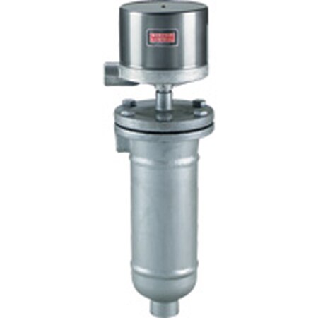
The Dwyer Series 1221, 1223, and 1224 are flanged chamber external mount liquid level switches designed for heavy-duty industrial environments. These units operate via a magnetic plunger mechanism attached to a removable stainless steel float within the chamber. The series is engineered for applications requiring operation at specific gravities as low as 0.40, making them suitable for oil and chemical processing.

Documented application contexts include:

  • Oil refineries
  • Chemical plants
  • Power generating stations
  • Other industrial environments requiring high-pressure level control

Operating Conditions & Performance

The series is rated for process pressures up to 1000 psig (69 bar) at 100°F (38°C), with a derated pressure of 850 psig (59 bar) at temperatures reaching 475°F (246°C). The minimum specific gravity supported is 0.40. Ambient operating temperature limits are specified up to 212°F (100°C).

Performance characteristics include a repeatability of ±1/4" (6.4 mm) and switch level changes that vary by specific gravity, with the "A*" dimension noted as not adjustable in two-stage configurations.

Pressure Ratings by Model

  • Type 1221: 1000 psi at 100°F; 850 psi at 475°F Max. (Carbon steel body, side/bottom process connections).
  • Type 1223: Available with 1" flanges in 150#, 300#, and 600# classes for side/bottom connections.
  • Type 1224: Available with 1" flanges in 150#, 300#, and 600# classes for side/side connections.

Configuration Options

The series offers extensive configuration options across enclosures, circuit arrangements, materials of construction, and process connections to meet specific installation requirements.

Enclosure Ratings & Materials

  • G (General Purpose): NEMA-1; painted steel and aluminum.
  • WT (Weather Proof): NEMA-3R, 4, 4X; painted steel, aluminum, neoprene. Recommended for high humidity or outdoor service with H2 option.
  • E (Explosion-proof): NEMA-7, 9, Class I Groups B, C, D, Class II Groups E, F, G (CSA approved Groups C, D, E, F, G only); aluminum construction. Includes breather and drain with H2 option.
  • EV (Explosion-proof Vapor-proof): NEMA-7, 9, Class I Groups B, C, D, Class II Groups E, F, G; aluminum and neoprene.

Circuit Configurations & Outputs

The series supports single-stage or two-stage operation with the following contact types:

  • Mercury Contacts (48XX): SPST, SPDT, DP-ST, and DP-DT configurations. Ratings include 10A at AC 120V/DC 125V for single-stage.
  • Snap-Action Contacts (78XX): Hermetically sealed or standard snap switches in SPDT and DPDT arrangements. Includes high capacity DC options (98XX) requiring heat fins if process temperature exceeds 350°F (177°C).

Process Connections & Materials

  • Standard 1" NPT hubs or optional flanged connections (150#, 300#, 600#). A 1" socket weld hub is available as an option.
  • Wetted Materials: Carbon steel chamber with trim options including 303SS, 304SS, 316SS, and 430SS. The float is constructed of stainless steel.

Key Product Differences

The primary distinctions between models in this series relate to the chamber construction and process connection orientation:

  • Type 1221: Features a flanged carbon steel chamber with side/bottom process connections via 1" NPT hubs. Rated for pressures up to 1000 psig.
  • Type 1223: Designed with flanged process connections on the side and bottom, available in various pressure classes (150#, 300#, 600#).
  • Type 1224: Similar to Type 1223 but configured for side/side flanged process connections.

All models share the same minimum specific gravity of 0.40 and utilize removable stainless steel floats for inspection and maintenance. Electrical ratings vary by circuit code, with special order options available for 440V service (identified by changing the first digit in the ordering code).

  • bvseo_sdk, java_sdk, bvseo-4.0.0
  • CLOUD, getReviews, 5ms
  • REVIEWS, PRODUCT
  • bvseo-msg: The resource to the URL or file is currently unavailable.;
  • bvseo_sdk, java_sdk, bvseo-4.0.0
  • CLOUD, getContent, 30ms
  • QUESTIONS, PRODUCT
  • bvseo-msg: The resource to the URL or file is currently unavailable.;
EXAMPLE 1221 WT 7810 C1 40   1221-WT-7810-C1-40 Liquid Level Control, weatherproof enclosure, SPDT snap switch, fixed deadband, automatic reset, operating pressure 1000 psig (69 bar) at 100°F (38°C), 850 psig (59 bar) at 475°F (246°C), side/bottom process connections, 1" NPT, minimum specific gravity 0.40.
CONNECTION 1221           One Vertical and One Horizontal 1" NPT
1223           One Vertical and One Horizontal Flanged Connection
1224           Two Vertical Flanged Connections
1224T            
ENCLOSURE    G         General Purpose, NEMA 1
  WT         Weatherproof, NEMA 3R, 4, 4X
  E         Explosion-proof, NEMA 7, 9, Class I Groups B, C, D, Class II Groups E, F, G. CSA approved Groups C, D, E, F, G only.
  EV         Explosion-proof/Vapor-proof, NEMA 7, 9, Class I Groups B, C, D, Class II Groups E, F, G. CSA approved Groups C, D, E, F, G only.
CIRCUITS
(for electrical circuits
see charts A & B below)
    48XX       Single Stage Mercury Switch, see chart A
    48XX-XX       Two Stage, Mercury Switch, see chart A
    78XX       Single Stage, Snap Switch, see chart B
    78XX-XX       Two Stage, Snap Switch, see chart B
    78XXHM       Hermetically Sealed Snap Switch, see chart B
    98XX       Single Stage, High Capacity DC Snap Switch, use heat fins (HF) if process temperature exceeds 350°F (177°C), do not exceed 450°F (232°C), see chart B
    98XX-XX       Two Stage, High Capacity DC Snap Switch, use heat fins (HF) if process temperature exceeds 350°F (177°C), do not exceed 450°F (232°C), see chart B
CHAMBER MATERIAL       C1     Carbon Steel Body
      C216     316SS Body
      HFC1     Heat Fins & Carbon Steel Body
MINIMUM
SPECIFIC
GRAVITY
        40   0.40 Specific Gravity (1221 only)
        140   0.40 Specific Gravity & 150# Flange (1223, 1224 only)
        340   0.40 Specific Gravity & 300# Flange (1223, 1224 only)
        640   0.40 Specific Gravity & 600# Flange (1223, 1224 only)
OPTIONS           H2 H2 Socket Weld Hub (1221, steel housing only)
          STW SS Tag Wired
          01 Breather Only (E-Housing only)
          02 Drain Only (E-Housing only)
          12 Breather & Drain (E-Housing only)
          23720 Fungus Proofing

CHARTS A & B - ELECTRICAL CIRCUITS AND RATINGS
SWITCH TYPE SWITCH ACTION ELECTRICAL RATINGS IN AMPS ORDERING CODE
AC DC SINGLE STAGE TWO STAGE
120V 240V 440V 30V 125V 250V LOWER UPPER
CHART A
Mercury Contacts
SP-ST open on level FALL 10 5 3†   10 5 -4820 -4820 -21
SP-ST open on level RISE 10 5 3†   10 5 -4821 -4821 -20
SP-DT one switch 4 2 1†   4 2 -4810 -4810 -10
SP-DT two switches E.I.* 10 5 3†   10 5 -4815 -4815 -15
DP-ST two switches E.I.* open on level FALL 10 5 3†   10 5 -4814 -4814 -13
DP-ST two switches E.I.* open on level RISE 10 5 3†   10 5 -4813 -4813 -14
DP-DT two SP-DT switches 4 2 1†   4 2 -4806 -4806 -06
CHART B
snap action contacts
SP-DT one switch 12 5 3†   0.5** 0.25** -7810 -7810 -10
DP-DT two SP-DT switches 12 5 3†   0.5** 0.25** -7806 -7806 -06
SP-DT one hermetically sealed switch 5 5   5**     -7810HM -7810HM -10HM
DP-DT two hermetically sealed SP-DT switches 5 5   5**     -7806HM -7806HM -06HM
DP-DT two SP-DT switches 10 3     10‡ 3‡ -9806 -9806 -06
SP-DT one switch 10 3     10‡ 3‡ -9810 -9810 -10
†Available on special order, change 1st digit in ordering code from 4 to 5 or 7 to 8, i.e., -4820 becomes -5820, -7810 becomes -8810, etc.
‡10 amp inductive (polarized) at 125 VDC.
*Electrically Independent.
**Resistive.
en-US
en
Save Configuration