Need assistance? Call us: 1-800-663-4209



DRST-BG-Load-Cell-Cond
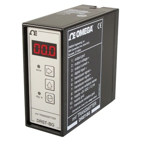
DIN RAIL Signal Conditioner for Load Cells
Models In Stock
- Load cell & Strain Gage Amplifier
- MV to Current/Voltage Conversion
- Front-Programmable/LED Display
- Relative Calibration of Input Span
DRST-BG-Load-Cell-Cond
From
$
665.28
Models In Stock

Product Overview
- Approvals Note EMC 2014/30/EU EAC: TR-CU 020/2011
- Calibration Temperature, Max 28 °C
- Calibration Temperature, Min 20 °C
- Display Type LED
- Electrical Output 0 to 20 mA
- Enclosure Ratings IP50
- Height 80.5 mm
- Length 84.5 mm
- Linearity Error < 0.1% of span
- Load Resistance 230 mA Max;Current Output : 600 Ω
- Mounting DIN Rail Mount
- Noise Calibration >60 dB
- Operating Temperature, Max 60 °C
- Operating Temperature, Min -20 °C
- Power Consumption 7.2 W
- Power Dissipation 2.2 W
- Relative Humidity <95% RH
- Series ID DRST-BG-Load-Cell-Cond
- Signal Dynamics Input 17 bit
- Signal Dynamics Output 16 bit
- Stability Load Stability: 0.01% of span/100 Ω
- Supply Power Type DC
- Update Rate 20 ms
- Weight 130 g
- Width 35.5 mm
Supported Applications
The Omega DRST-BG is a microprocessor-controlled, front-programmable mV transmitter designed for load cell applications. It converts bipolar millivolt signals from transducers into standard current or voltage outputs suitable for data acquisition and control systems.
Documented application areas include:
- Tank filling and draining
- Weighing operations
- Cable tensile force measurement
- Level control
Operating Conditions & Performance
The DRST-BG accepts a bipolar input range of -40...100 mV from transducers. The unit provides 17-bit signal dynamics on the input and 16-bit resolution on the output, with an updating time of 20 ms. Response time is programmable between 0.06 s and 999 s.
Performance specifications include a linearity error of ≤ ±0.1% of span and a temperature coefficient of < ±0.01% of span / °C (calibrated at 20...28°C). The effect of supply voltage change is specified as < ±0.002% of span / %V, with an EMC immunity influence of < ±0.5% of span.
Operating conditions require a power supply of 19.2...28.8 VDC and an ambient temperature range of -20°C to +60°C. The unit operates in relative air humidity up to < 95% RH (non-condensing). Internal consumption is rated at 2.2 W, with a maximum consumption of 7.2 W.
Configuration Options
The DRST-BG series supports configurable output signals and excitation voltages via front programming. Key capabilities include:
- Output Signals: Selectable between 0...20 mA or 0...10 V.
- Excitation Voltage: Front-programmable range of 5...13 VDC for transducer supply, with a maximum load capacity of 230 mA.
- Calibration Features: Supports relative calibration and taring via digital input or front key to set 0% and 100% scale without requiring equivalent physical loads.
The unit features an IP50 protection degree and utilizes a standard DIN rail form factor with overall dimensions of 80.5 x 35.5 x 84.5 mm (HxWxD). Electrical connection is provided via an 11-pin terminal block.
Key Product Differences
The series is identified by the model number guide DRST-BG and carries CE and EAC approvals. The single enumerated variant, SKU DRST-BG, represents the standard configuration for this DIN rail signal conditioner family as described in the user manual.
PDFs & Manuals


Show Ratings & Reviews
The DRST-BG says that is it capable of 10V output with JP2 ON (connecting the 500ohm) and J2 OFF. It looks like J1 and J2 are internal. Is this true. Do we need to physically open the box and manually change the jumpers in order to get 10V output?
Thank you for your question. We will require more information to help on this question, please email the DAS team at DAS@dwyeromega.com
Date published: 2024-10-16
How would I connect wires to this signal conditioner? Are there screw terminals on the back?
There are a series of numbered screw terminals on the back of this unit. They are identified by a table printed on the side of the case and also in the user's manual.
Date published: 2024-10-25