Need assistance? Call us: 1-800-663-4209



Series-AT-605Configuration
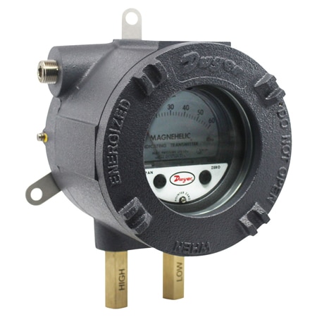
ATEX/IECEx Magnehelic® Differential Pressure Transmitter – 4-20 mA
- ATEX/IECEx housing provides all the capabilities and values of the Series 605
- Magnehelic® transmitter in a flame and explosion-proof enclosure
- Quick response to pressure changes means no delay in assessing critical situations
- Durable and rugged housing and high-quality components combined provide long service life and minimize downtime
- High impact strength and high temperature rated for applications where hazardous environments exist
- Increased response time at low pressures with LD port configuration


Product Overview
- Series ID Series-AT-605
Supported Applications
The Series AT-605 ATEX/IECEx Magnehelic® Differential Pressure Indicating Transmitter is designed for the visual monitoring and electronic control of very low differential pressures in hazardous locations. It measures positive, negative, or differential air pressure and non-combustible, compatible gases. The unit provides local analog indication on a large scale while converting pressure into a standard two-wire 4-20 mA signal.
Operating Conditions & Performance
The Series AT-605 operates within an ambient temperature range of 32 to 120°F (0 to 48.9°C). It is powered by a 10-35 VDC supply in a two-wire configuration with a maximum load resistance of 0 to 1250 Ω max. The transmitter features flameproof enclosures rated IP66, or IP65 for versions VS1/VS2/VL1.
Measurement ranges span from low differential pressures such as 0-60 Pa and 0.05-0.20 in w.c., up to higher spans including 0-500 Pa and 0-50 in w.c. Accuracy specifications vary by model range, with electrical accuracy values documented as ±0.5%, ±2%, ±3%, or ±4% of full scale depending on the specific configuration.
Pressure limits are defined by port/valve configurations: VS0 and VL0 support 10 kPa; VS1 and VL1 support 20 kPa (one port) / 15 kPa (both ports); and VS2 supports 40 kPa (one port) / 20 kPa (both ports). Response time is noted to increase at low pressures with the LD port configuration.
Approvals & Certifications
- ATEX Certificate: INERIS 21ATEX0033X
- IECEx Certificate: IECEx INE 21.0064X
- Compliance (Gas): ATEX: Ⅱ 2G Ex db IIC T5, T6 Gb (-60°C≤Ta≤+50°C for T6; -60°C≤Ta≤+60°C for T5); IECEx: Ex db IIC T5, T6 Gb
- Compliance (Dust): ATEX: Ⅱ 2D Ex tb IIIC T75°C Db; IECEx: Ex tb IIIC T75°C Db
Configuration Options
The series offers configurable options for housing, viewing, port materials, and valve configurations to suit specific installation needs.
Housing & Viewing Options
- Enclosure Material: Aluminum (102NA)
- Cover Type: Blind cover or Glass window for viewing the gage face
- Dimensions: 7-1/64" [182] width, 6-3/16" [157] depth, 6-1/5" [165] height (excluding cable entry)
Port & Valve Configurations
- Process Connections: Two 1/8" female NPT ports; brass standard, stainless steel optional.
- Cable Entry: Two 1/2" NPT female (ANSI/ASME B1.20.1); cable gland not included.
- Configurations:
- VS0: STD port/no valve
- VL0: LD port/no valve
- VS1: STD port/STD valve
- VS2: STD port/LD valve
- VL1: LD port/LD valve
Range Selections
The model number includes a range code defining the measurement span. Available ranges include:
- Inches of Water Column (in w.c.): 0-50, 0-1.0, 0-2.0, 0-3.0, 0-6.0, 0-10, 0-20.0, 0-30, and differential spans such as 0.05-0.20 or 0.25-0.25.
- Pascals (Pa): 0-60, 0-125, 0-250, 0-500.
Electrical & Mechanical Features
- Output Signal: 4-20 mA (two-wire)
- Adjustment: SPAN and ZERO knobs for calibration checks; do not adjust unless necessary.
- Wetted Materials: Consult factory
Key Product Differences
The Series AT-605 is distinguished from the standard Series 605 by its ATEX/IECEx approved flameproof enclosure, making it suitable for hazardous locations. While both series utilize Magnehelic® mechanical design and offer similar measurement ranges, the AT-605 includes specific certifications (INERIS 21ATEX0033X / IECEx INE 21.0064X) and enclosure ratings not present in non-hazardous versions.
Variations within the Series AT-605 are defined by the model number structure: AT-Housing Material-Series Code-Range-Cover Type-Port/Valve Config. For example, a unit with code AT-102NA-605-00N-W1VS012 specifies an aluminum enclosure (102NA), Series 605 transmitter, 0.05-0.20 in w.c. range (00N), glass window cover (W1), and a standard port with no valve configuration (VS0) using two 1/2" NPT cable entries.
Pressure limits vary significantly based on the selected port/valve code; for instance, VS2 allows higher pressure ratings than VL1. The series is not field repairable and must be returned to the factory if service is required.
PDFs & Manuals
Accessories
Static Pressure Sensors for Manometers & Gages across Air Filters
From $2.55
0 In Stock
Industrial Control: Pressure Gauges, Flow Meters & Temp Controllers
From $4.00
0 In Stock
Show Ratings & Reviews
-
 70147000_dwg_dwg
-
 70147000_pdf_pdf
-
70147010_dwg_dwg
-
70147010_pdf_pdf
-
70147020_dwg_dwg
-
70147020_pdf_pdf
-
70147030_dwg_dwg
-
70147030_pdf_pdf
-
70147040_dwg_dwg
-
70147040_pdf_pdf
-
70147001_dwg_dwg
-
70147001_pdf_pdf
-
70147011_dwg_dwg
-
70147011_pdf_pdf
-
70147021_dwg_dwg
-
70147021_pdf_pdf
-
70147031_dwg_dwg
-
70147031_pdf_pdf
-
70147041_dwg_dwg
-
70147041_pdf_pdf