Need assistance? Call us: 1-800-663-4209



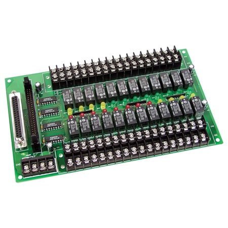
OME-DB-24R-24RD
24-Channel Relay Output Board - Panel Mount
Models In Stock
- 24 Form C SPDT Relays
- OPTO-22 Compatible Connector
- Connects Directly to OME-DIO-24, OME-DIO-48, OME-DIO-144 or Other OPTO-22 Compatible Digital Output Board
- Switch up to 0.5A at 120 Vac Switch up to 1A at 24 Vdc
OME-DB-24R-24RD
From
$
546.43
Models In Stock


Product Overview
- Control Output 24 Form C SPDT
- Cycle Time 6 ms
- Electrical Life 2 x 10^5 cycles
- Height 132 mm
- Logic TTL Relay On
- Mechanical Life 2 x 10^7 cycles
- Number of Channels 24
- Operating Temperature, Max 60 °C
- Operating Temperature, Min 0 °C
- Power Consumption +12 V @ 528 mA ; +5 V @ 150 mA
- Relative Humidity 5 to 90 % RH non-condensing
- Relay Current 1 A
- Series ID OME-DB-24R-24RD
- Storage Temperature, Max 70 °C
- Storage Temperature, Min -20 °C
- Switching Voltage 120/60 Vac/Vdc
- Voltage Source 0.5 A/120 Vac, 1 A /24 Vdc
- Width 225 mm
Supported Applications
The Omega OME-DB-24R and OME-DB-24RD series are 24-channel relay output boards designed for I/O control applications. These daughter boards feature on-board relay driver circuits and connect directly to the OME-DIO-24, OME-DIO-48, or OME-DIO-144 digital output boards, as well as other OPTO-22 compatible systems. The series provides isolated switching for external loads via Form C SPDT relays.
Operating Conditions & Performance
The relay elements are rated for a nominal load of 0.5 A @ 120 Vac or 1A @ 24 Vdc, with maximum switching limits of 60 VA and 24 W. Maximum switching voltage is specified at 120 Vac or 60 Vdc, while the maximum switching current is 1A. The mechanical life expectancy is listed as 2 x 10^7 operations, and electrical life expectancy is 2 x 10^5 operations.
Control logic requires a TTL high (+5 V) input to activate the relay (relay on). Power consumption for the board is +12 V @ 528 mA max or +5 V @ 150 mA max. The series operates within an ambient temperature range of 0 to 60°C (32 to 140°F) and a storage temperature range of -20 to 70°C (-4 to 158°F). Humidity ratings are specified as 5 to 90% RH non-condensing. The relay operate time is documented at 6 ms.
Power Requirements
To avoid overloading a PC's power supply, the board requires an external +12 Vdc or +24 Vdc power supply.
Configuration Options
The series is available in two primary configurations distinguished by their connector interfaces:
- OME-DB-24R: Features one 50-pin header compatible with OPTO-22 connectors.
- OME-DB-24RD: Includes both a 50-pin header and a 37-pin D-sub connector for expanded connectivity options.
Voltage versions are offered in +12 V or +24 V configurations. Mounting flexibility is provided through optional DIN-rail mounting kits available for both the OME-DB-24R and OME-DB-24RD models. The physical dimensions of the board are 132 H x 225 mm W (8.1 x 4.5").
Accessories and Cables
The series supports various cabling options to facilitate connection:
- OME-CA-5015: 50-pin flat cable, 1.5m (5').
- OME-CA-3710: 37-pin male-male D-sub connector cable, 1 m (3').
- OME-CA-3720: 37-pin male-male D-sub connector cable, 2 m (7').
Screw terminals are included for easy field wiring of the relay outputs.
Key Product Differences
The OME-DB-24R and OME-DB-24RD models differ primarily in their connector topology. The OME-DB-24R utilizes a single 50-pin header, whereas the OME-DB-24RD adds a 37-pin D-sub connector alongside the standard 50-pin header.
Model numbers indicate voltage and mounting configuration:
- /12: Denotes the +12 V version (e.g., OME-DB-24R/12).
- /24: Denotes the +24 V version (e.g., OME-DB-24R/24).
- /DIN: Indicates inclusion of a DIN-rail mounting kit.
Each board includes an operator's manual on CD ROM. The series is covered by the standard 1-year warranty, with the OMEGACARE™ extended warranty program available to extend coverage to a total of 2 years for parts and labor.
PDFs & Manuals



Show Ratings & Reviews
On page 26 of the manual, the numbering on the right side of the 37-pin D-sub connector seems non-standard. Should standard D-sub numbering (1-19, bottom to top) be used?
Thank you for your question. We will require more information to help on this question, please email the DAS team at DAS@OMEGA.COM
Date published: 2021-09-30
The manual doesn't provide mounting hole spacing, only outer board dimensions. Can you provide the hole spacing since there are no CAD models?
Thank you for your questions. Diameter is 4mm for the holes. Spacing is 210mm and 122mm.
Date published: 2024-05-21
Do you offer a ACAD download of the 24-Channel Relay Output Board?
Thank you for your question. We do not provide a Cad drawing just dimensions in the manual you can download from the website.
Date published: 2021-02-05
Does this board require an external 5V power supply in addition to 12/24V? I am unsure if the +5V lines shown on page 26 of the manual are for supply or reference.
Hello
Regarding your question, if you are referring to the +5VDC on the board, that is to specifically power up the relays on the board, whereas the 12VDC/24VDC connection is to power up the board itself.
Date published: 2021-10-05