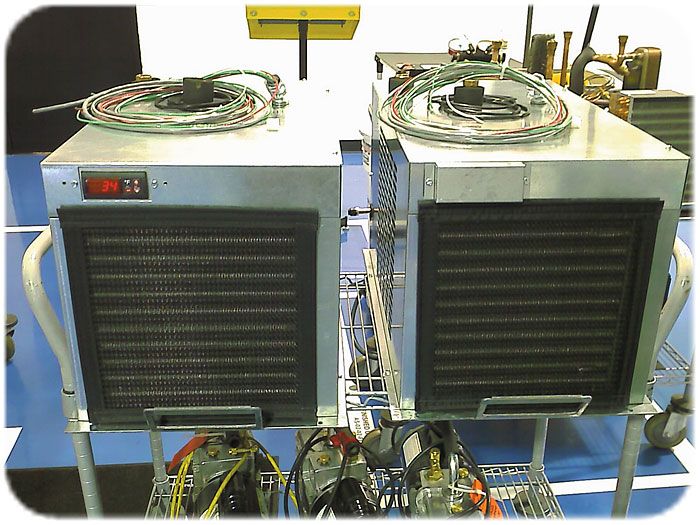
Water chillers are cooling systems that remove heat from a circulating liquid, typically water or a water-glycol mixture, and supply that cooled fluid to equipment or spaces that require precise temperature control. They are widely used in HVAC and industrial applications where consistent, repeatable cooling is critical.
From maintaining comfort in commercial buildings to preventing overheating in data centers and supporting specialized industrial processes, chilled water systems quietly play a vital role in the infrastructure that supports everyday life.
Primary Types of Water Chillers
There are two primary categories of water chillers: absorption chillers and refrigerant (vapor-compression) chillers. While both serve the same purpose, they rely on fundamentally different cooling processes.
Absorption Chillers
Absorption chillers use a heat source, such as natural gas, or steam, to drive the refrigeration cycle. Instead of mechanical compression, these systems rely on chemical absorption and desorption to circulate the refrigerant. Absorption chillers are typically used in applications where low-cost or recovered heat is readily available.
Refrigerant (Vapor-Compression) Chillers
Refrigerant compression chillers are the most common type of water chiller. These systems use mechanical compression to move heat and consist of four primary components:
- Compressor
- Evaporator
- Condenser
- Metering or Expansion Device
The refrigerant absorbs heat from the chilled water in the evaporator. The compressor then raises the pressure and temperature of the refrigerant vapor. Heat is rejected in the condenser, after which the refrigerant condenses back into a liquid and passes through the metering device before returning to the evaporator to repeat the cycle.
Condenser Cooling Methods: Air-Cooled vs Water-Cooled
Refrigerant compression chillers are further classified based on how heat is rejected at the condenser.
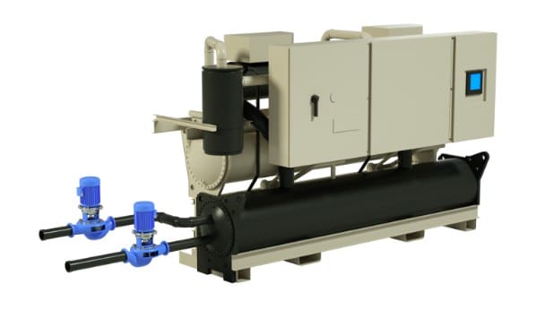
Water-Cooled Chillers
Water-cooled chillers use a secondary water loop to remove heat from the condenser. This heat is typically rejected through a cooling tower, pond, or nearby body of water. These systems are usually installed indoors and are common in larger facilities where higher efficiency and greater cooling capacity are required.
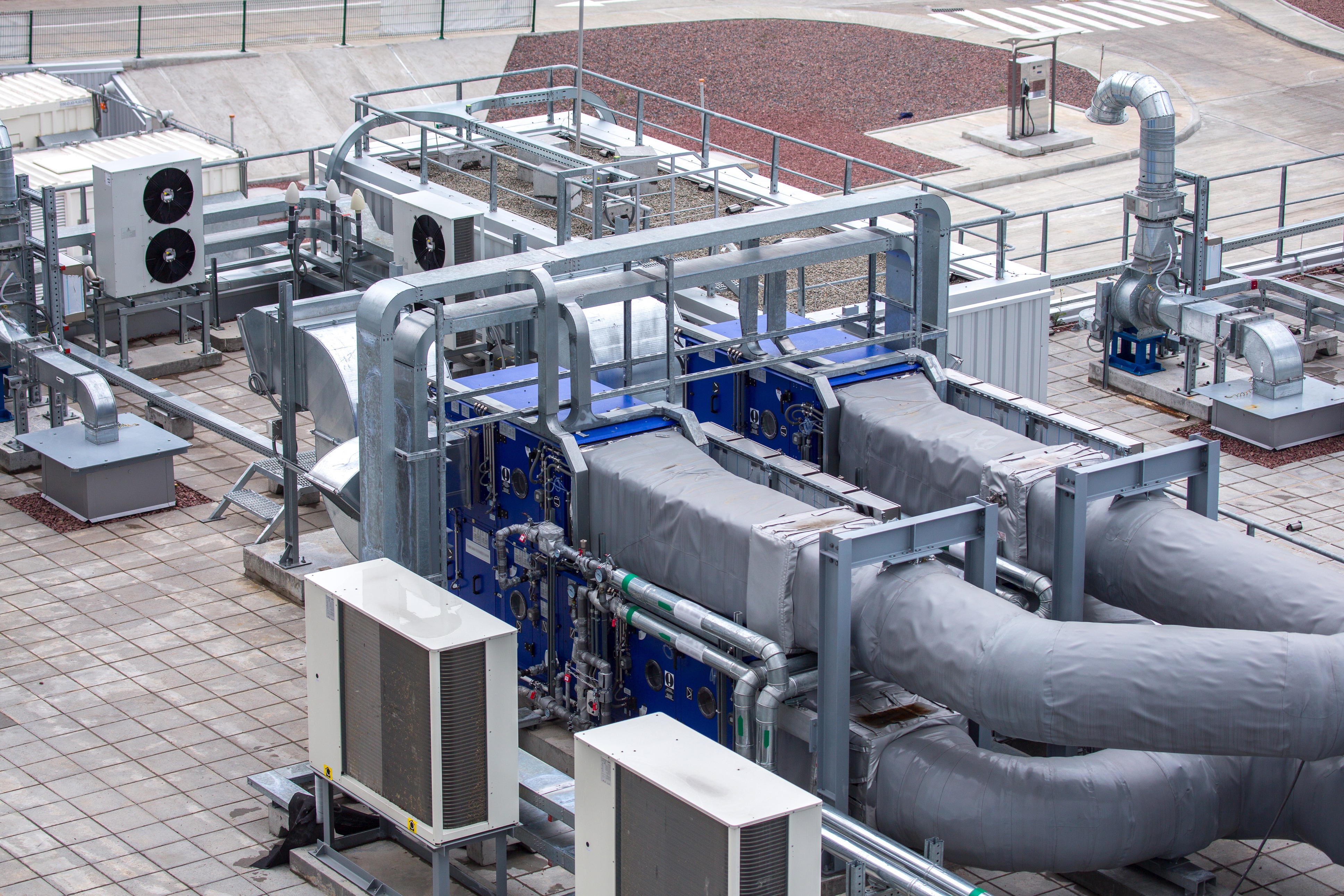
Air-Cooled Chillers
Air-cooled chillers reject heat directly to the atmosphere using ambient air and fans. The refrigeration cycle remains the same as in water-cooled systems, but air replaces water as the cooling medium at the condenser. These chillers are designed for outdoor installation and do not require cooling towers, reducing system complexity and maintenance requirements.
Compressor Types and Capacity Control
The compressor is the primary component that defines how a chiller operates, how it modulates capacity, and how it responds to changing load conditions. Four common compressor types are used in water chillers, each offering distinct performance characteristics.
Reciprocating Compressors
Reciprocating compressors operate using pistons and a crankshaft, similar to an internal combustion engine. As the pistons compress the refrigerant gas, its temperature increases and the hot vapor is discharged to the condenser.
Capacity control is achieved through intake and exhaust valves that can unload cylinders as demand decreases. This makes reciprocating compressors well suited for applications with large swings in cooling demand or extended periods of low load, such as offices or schools. Typical capacities range from 20 to 125 tons, with some systems reaching up to 450 tons.
Centrifugal Compressors
Centrifugal compressors operate using a high-speed impeller, similar to a centrifugal pump. These compressors are capable of delivering very high cooling capacities in a compact footprint.
They can continuously vary capacity with near proportional changes in power consumption, making them highly efficient for large systems requiring tight temperature control. Centrifugal chillers are commonly used in large facilities and can range from approximately 150 to 2,400 tons.
Rotary Screw Compressors
Rotary screw, or helical, compressors use two precisely machined, intermeshing rotors to compress the refrigerant through volume reduction. Because of the tight tolerances required, these systems generally have a higher initial cost.
Capacity is controlled using a sliding inlet valve or a variable-speed drive. Rotary screw compressors typically range from 25 to 450 tons, with some designs capable of reaching 800 tons.
Rotary Scroll Compressors
Rotary scroll compressors use two spiral elements to compress the refrigerant. One scroll remains fixed while the other orbits eccentrically, trapping and compressing pockets of refrigerant between the scrolls.
Scroll compressors are commonly used in smaller chiller systems and are valued for their quiet operation, reliability, and relatively simple mechanical design.
Importance of Chilled Water Flow
For effective heat transfer between the circulating water and the refrigerant, sufficient and stable water flow through the chiller is essential. Recommended chilled water flow velocities typically range from 3 to 12 feet per second.
Maintaining proper flow helps ensure efficient heat transfer, stable system performance, optimized energy usage, and long-term reliability of the chiller components.
Methods for Proving Flow Through Chillers
Numerous methods exist for proving flow through chillers, each offering specific advantages depending on system requirements, accuracy needs, installation constraints, and cost considerations. These methods are commonly used to ensure sufficient water flow for proper heat transfer, equipment protection, and efficient system operation.
Differential Pressure Measurement
Differential pressure (DP) measurement is one of the most widely used methods for proving flow through a chiller. As fluid flows through the chiller, a pressure drop occurs between the inlet and outlet. This pressure differential is directly related to flow rate, with higher flow producing a higher differential pressure.
Several instruments can be used to measure this pressure difference, most commonly differential pressure switches and differential pressure transmitters.
Differential Pressure Switch
A differential pressure switch is installed across the chiller inlet and outlet. The switch setpoint is adjusted to actuate at a predetermined differential pressure that corresponds to an acceptable minimum flow rate. When the pressure drop exceeds this threshold, the switch confirms adequate flow.
Advantages
- Adjustable setpoint
- No external power required
- Low cost
- Simple operation
- No moving parts
Differential pressure switches are often used for basic flow proofing and interlocks where on/off confirmation is sufficient.
Differential Pressure Transmitter
A differential pressure transmitter is also installed across the chiller but provides a continuous analog signal representing the measured pressure differential. These devices require power and typically output a 4–20 mA or 0–10 VDC signal, which can be monitored by a control system or building management system.
Advantages
- Accurate indication of flow conditions
- Linear analog output for monitoring or control
- No moving parts
Differential pressure transmitters are well suited for applications where trending, diagnostics, or tighter control is required in addition to flow verification.
Vane Flow Switch
A vane flow switch is an insertion-style device installed directly into the pipe. The vane extends into the flow stream and actuates a switch once sufficient flow causes the vane to deflect. The vane length is typically trimmed or adjusted based on pipe size and expected flow rate.
Advantages
- Low cost
- Easy installation
- Simple operation
Vane flow switches are commonly used for basic flow confirmation in chilled water systems where moderate accuracy is acceptable.
Thermal Dispersion Flow Switch
A thermal dispersion flow switch uses heat transfer principles to prove flow. The probe is heated slightly above the process temperature, and the rate at which it cools depends on the fluid velocity. When sufficient flow is present, the heat is carried away more rapidly, indicating flow conditions above the set threshold.
Advantages
- Easy installation
- No moving parts
- Low pressure drops due to small insertion depth
- Simple operation
Thermal dispersion flow switches are often selected for applications requiring reliable flow proofing with minimal impact on the piping system.
Innovative Solutions from

Series DX Wet/Wet Differential Pressure Switch
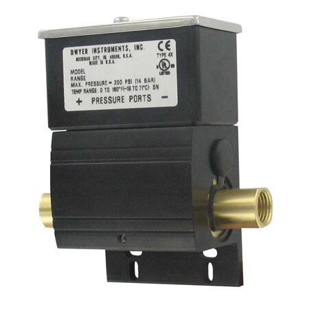
The Series DX Wet/Wet Differential Pressure Switch provides contact output based on the differential between two pressure sources in liquid or gas systems. Brass and fluoroelastomer wetted materials make it suitable for most gases and water-based solutions.
Designed for low differential pressure applications, the switch offers adjustable set points as low as 1 psid on decreasing pressure and up to 75 psid on increasing pressure, with a high static pressure rating of 200 psig. A weatherproof UL Type 4X enclosure allows use in outdoor, wash-down, and dust-laden environments. Installation is simplified with an externally adjustable set point, integral mounting flange, and removable terminal block.
Common Applications
- Filter condition indication
- Proof of flow monitoring
- Pump, chiller, and heat pump flow verification
Series 3100D Smart Differential Pressure Transmitter
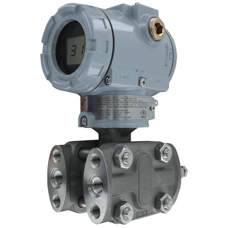
The Mercoid® Series 3100D Smart Pressure Transmitter is a microprocessor-based, high-performance device designed for differential pressure and level measurement in industrial and hazardous area applications. Configuration is performed using onboard zero and span pushbuttons or via HART® communication, eliminating the need for a field calibrator and reducing installation and commissioning time.
Advanced transmitter software compensates for thermal effects to improve accuracy and stability, while EEPROM memory retains configuration settings and sensor correction data during power loss. With FM approval for hazardous locations and a 100:1 rangeability, the Series 3100D offers flexibility to adapt to a wide range of process requirements.
Common Applications
- Flow measurement
- Level monitoring
- Filter and pump differential pressure
- Critical process monitoring
Series FS-2 Vane Flow Switch

The Series FS-2 Vane Flow Switch provides a simple and economical solution for flow proving in liquid piping systems. Designed for use in pipes ranging from 1 to 8 inches, the adjustable vane allows the switch to be tailored to a wide range of flow conditions without special tools.
Field-adjustable vane layers and a set point adjustment screw enable on-site customization to meet specific application requirements. An aluminum, weatherproof housing supports outdoor installation and long-term reliability in mechanical and process environments.
Common Applications
- Boiler flow proving
- Hot water heaters and chillers
- Cooling lines and machinery
- Liquid transfer systems
Series TDFS2 Thermal Dispersion Flow Switch
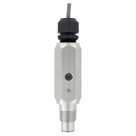
The Series TDFS2 Thermal Dispersion Flow Switch provides reliable flow indication by detecting whether flow is above or below a user-defined set point. Using thermal dispersion sensing, the switch offers accurate flow detection with minimal pressure drop due to its low-profile insertion design.
Two integrated LED indicators provide clear visual status feedback, while the flow set point is easily adjusted in the field using the included magnet. The device supports both normally open and normally closed NPN outputs, allowing flexible integration with control and monitoring systems.
Common Applications
- Boiler flow proving
- Hot water heaters and chillers
- Liquid transfer systems

What Is An Immersion Heater? Types Of Immersion Heating Elements What is an Immersion Heater?
what is an industrial electric heater? What is an industrial heater?