An anemometer is an instrument used to measure the speed, or velocity, of gases. It can be applied to contained flows, such as airflow inside a duct, or unconfined flows, such as atmospheric wind. To determine velocity, an anemometer measures changes in a physical property of the fluid or the effect the fluid has on a mechanical or thermal sensor placed in the flow.
Anemometers are used across a wide range of applications, including industrial process monitoring, laboratory research, and HVAC system testing.
Innovative Solutions from DwyerOmega


What Are Anemometers Used For?
Depending on the design and sensing method, an anemometer may be used to measure:
- Measuring wind speed for weather monitoring and forecasting
- Assessing wind conditions for aviation, maritime, and outdoor safety
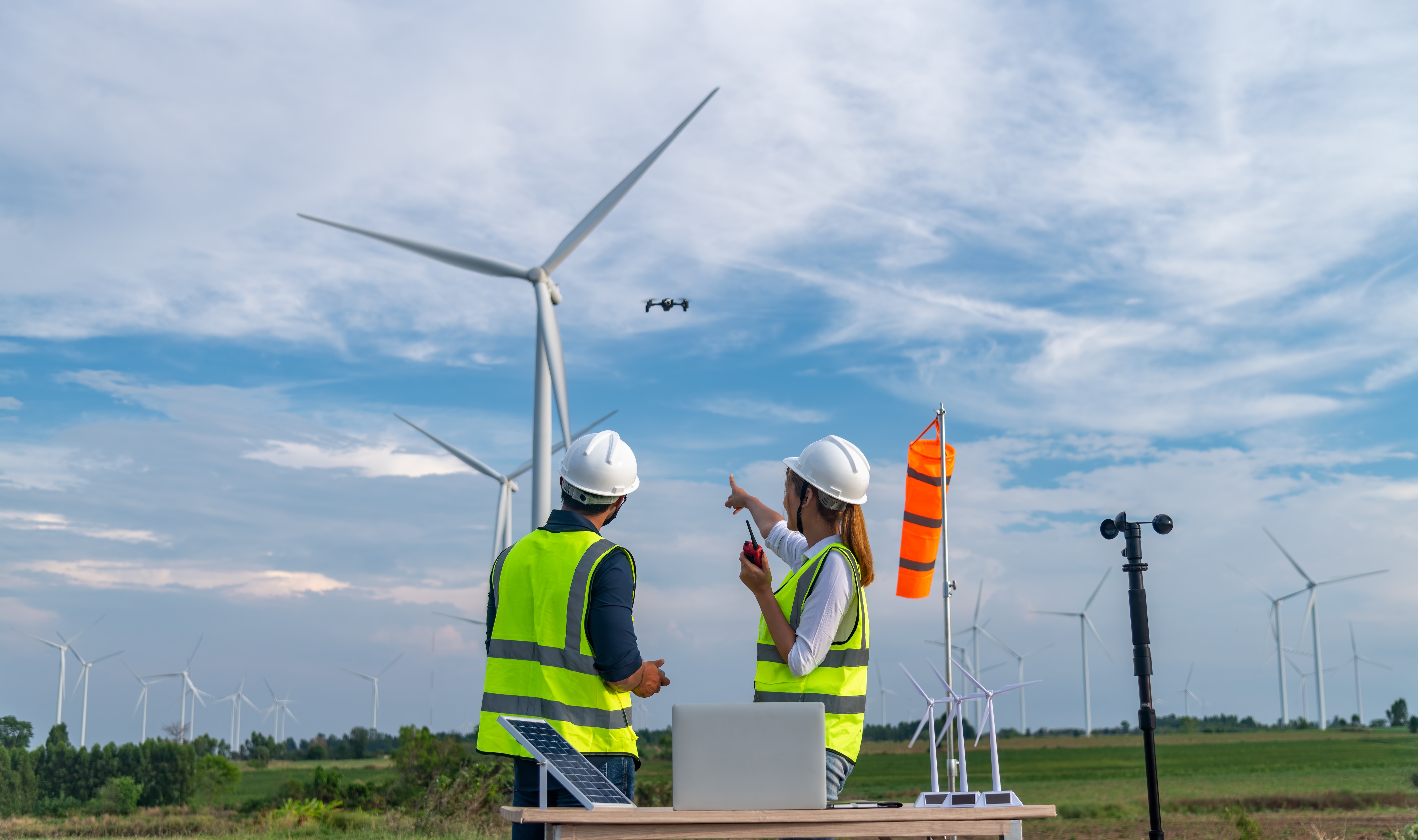
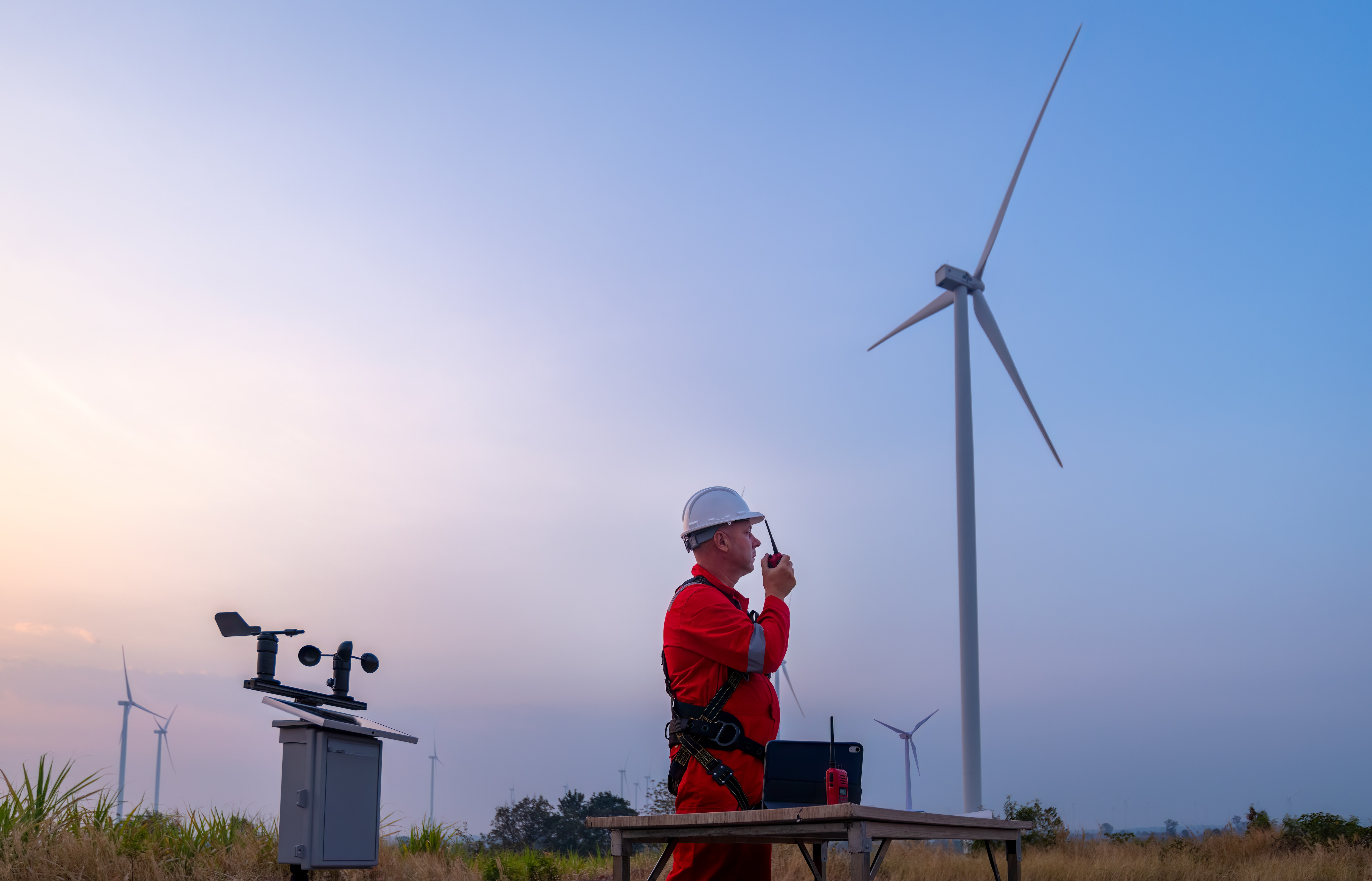
- Optimizing wind turbine performance and evaluating wind energy sites
- Monitoring airflow in HVAC systems, ducts, and cleanrooms
- Supporting environmental and climate research, including dispersion modeling
- Providing input to industrial process control where airflow affects quality or safety
- Aiding structural and civil engineering analysis, such as wind loading studies
Anemometer Operating Modes
Anemometers are often classified by their operating control method:
- Constant-Temperature Anemometers (CTA)
- Constant-Power Anemometers
Constant‑Temperature Anemometers vs. Constant‑Power Anemometers
Constant‑Temperature Anemometers
Constant‑Power Anemometers
Types of Anemometers
There is a wide range of anemometer models available for directly measuring wind and air velocity. Three common types are:
- Vane Anemometers
- Thermal (Hot-Wire) Anemometers
- Cup Anemometers
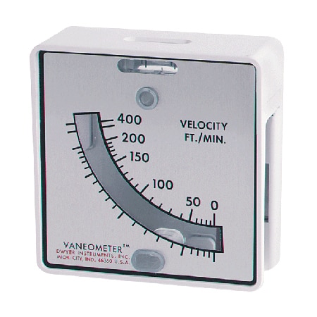
Vane Anemometers
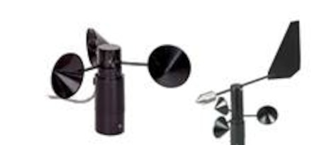
Vane anemometers are a form of rotating mechanical velocity sensor, sometimes referred to as vane- or propeller-type anemometers. In this design, the axis of rotation must be parallel to the direction of airflow, and it is therefore typically horizontal.
In open environments where wind direction varies, the instrument must be free to align itself with the flow direction. In applications where airflow direction is fixed (such as ventilation shafts, ducts, or building systems) vane anemometers, often referred to as air meters, provide reliable and repeatable results.
Many modern vane anemometers also offer additional measurement and calculation functions, including:
- Air temperature
- Relative humidity and dew point
- Volumetric airflow calculations
- Data logging and averaging
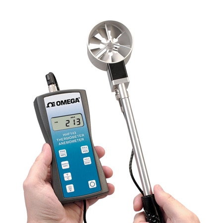
Thermal (Hot-Wire) Anemometers
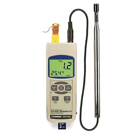
Thermal anemometers measure air velocity using heat transfer principles. A very fine wire or sensing element—typically only a few micrometers in diameter—is electrically heated above ambient temperature. As air flows past the sensor, it cools the element. Because the electrical resistance of most metals depends on temperature (tungsten is commonly used), airflow velocity can be inferred from changes in resistance.
Several thermal anemometer configurations exist, including:
- CCA (Constant-Current Anemometers)
- CVA (Constant-Voltage Anemometers)
- CTA (Constant-Temperature Anemometers)
Hot-wire anemometers are extremely delicate, but they offer exceptionally high frequency response and fine spatial resolution compared to most other airflow measurement methods. For this reason, they are widely used in research applications involving turbulent flows or rapidly fluctuating velocities.
Thermal anemometers are often available with additional capabilities such as:
- Air temperature measurement
- Data logging and statistical analysis
Cup Anemometers
Cup anemometers are one of the simplest and most recognizable anemometer designs. They typically consist of three or four hemispherical cups mounted on horizontal arms, which are equally spaced around a vertical shaft. Airflow striking the cups causes the assembly to rotate, and the rotational speed is proportional to wind speed.
Because one cup is always presented concave-side-first to the wind, the instrument rotates regardless of wind direction within the horizontal plane. Wind speed is calculated by counting the number of rotations over a given time interval.
Early designs, including those by Robinson, incorrectly assumed a fixed relationship between cup speed and wind speed. Later experimentation showed that this relationship—known as the anemometer factor—varies with cup and arm dimensions and generally falls between two and slightly over three.
Key historical developments include:
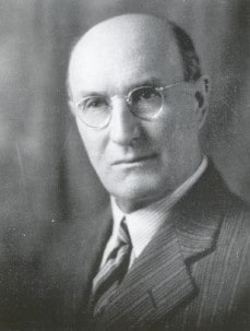
- John Patterson (1926): Developed the three-cup anemometer, which reduced error and improved responsiveness to gusts
- Brevoort & Joiner (1935): Further refined cup geometry to achieve linear response with less than 3% error up to 60 mph
- Derek Weston (1991): Modified the three-cup design to measure both wind speed and wind direction using cyclical speed variations

DwyerOmega | Blog | Doppler vs Transit Time Ultrasonic Flow Meters Understanding the Differences
DwyerOmega | Blog | How Accurate Are Air Flow Measurement Instruments? Methods, Tools, and Best Practices