
A strain gauge is a sensor that measures the amount of strain (deformation) in an object by converting mechanical force into a measurable change in electrical resistance. When external forces such as pressure, tension, compression, or weight are applied to a stationary object, they create internal resisting forces known as stress and physical deformation known as strain.
Strain gauges are among the most essential tools in electrical measurement techniques used to quantify mechanical quantitates. As their name implies, they are designed to measure strain, which can be tensile (expansion), compressive (contraction), or shear (parallel or tangential), depending on whether the applied force stretches, compresses, or otherwise distorts the material.
Understanding Stress and Strain
Strain in a material can result from external loads, pressure, torque, heat, or even internal material changes. Under the right conditions, the magnitude of strain can be directly correlated to the amount of stress or force acting on the material. This principle forms the basis of experimental stress analysis, where engineers use strain values measured on a component’s surface to determine the stress distribution, predict fatigue, and ensure long-term safety performance.
Strain Gauges: Construction and Working Principle
A typical strain gauge consists of three layers:
- A protective laminate top layer
- A thin metallic sensing element (usually a fine wire or foil)
- A plastic or polymer base
When bonded to a surface under a load, the strain gauge deforms along with it. This deformation causes a proportional change in the electrical resistance of the sensing element. The variation in resistance can be measured and converted —using established calibration equations—into an accurate strain value.
Understanding the Working Principle of a Strain Gauge
The working principle of a strain gauge is based on the piezoresistive effect, or the tendency of a material’s electrical resistance to change when it is stretched or compressed.
When a strain gauge is firmly bonded to the surface of a material under stress, it deforms in unison with that surface. This deformation alters the length and cross-sectional area of the gauge’s conductive element, producing a corresponding change in its electrical resistance.
The relationship between strain (ε) and resistance change is expressed by the strain measurement equation:
Where:
- ΔR = change in resistance
- R = original resistance
- K = gauge factor (a constant that depends on the material and construction of the strain gauge)
- ε = strain (unitless, often expressed in microstrain, µε = 10⁻⁶ strain)
In most strain gauges, the gauge factor (K) typically ranges from 2.0 to 2.2 for metallic foil types.
Wheatstone Bridge and Signal Conditioning
Because the change in resistance produced by a strain gauge is extremely small (often just a few hundredths of an ohm), a Wheatstone bridge circuit is used to precisely detect it. This circuit converts the resistance change into a proportional voltage output, which can then be amplified, digitized, and displayed as strain, force, or pressure.
The Wheatstone Bridge Configuration
A traditional Wheatstone bridge consists of four resistive arms arranged in a diamond-shaped network. A voltage source is applied across one diagonal of the bridge, and the output voltage is measured across the other.
When all four resistors have equal resistance, the bridge is balanced, and no output voltage is produced. When a strain gauge bonded to a structure experiences deformation, its resistance changes slightly, unbalancing the bridge and producing a measurable output voltage proportional to the applied strain.
There are three common configurations used in strain measurement:
Quarter-Bridge:
One active strain gauge and three fixed resistors. Used in single-direction strain measurements where temperature compensation is less critical.
Half-Bridge:
Two active gauges —one in tension and one in compression—mounted on opposite sides of the specimen. Provides better temperature compensation and doubled signal output.
Full-Bridge:
Four active gauges arranged so that opposite arms experience equal and opposite strain. Offers the highest sensitivity, noise rejection, and temperature compensation.
Signal Conditioning
The bridge’s output is typically in the millivolt range, so it must be amplified and conditioned before being processed. A strain gauge amplifier or signal conditioner performs key functions:
- Amplification: Boosts the low-level signal for accurate digitization
- Filtering: Removes electrical noise and drift
- Temperature Compensation: Adjusts for thermal expansion or contraction that could affect resistance
- Conversion: Translates the analog voltage into a digital signal for logging or display
Common Strain Gauge Configurations
Strain gauges are used to monitor how much stress a material or structure can withstand before failure. They come in various configurations depending on the application, including single-element, rosette, and biaxial designs. Selecting the right strain gauge depends on:
- The direction of the primary strain
- The type of strain being measured (tensile, compressive, or shear)
- The size and geometry of the target measurement area
In addition to differences in materials and sensing principles, strain gauges also vary by configuration—the physical layout and orientation of their sensing elements. Each configuration is optimized to measure a specific type or direction of strain, ensuring accuracy and relevance to the intended application.
Linear Strain Gauges
Linear strain gauges measure strain along a single axis and are ideal for applications where the direction of stress is known. They are the most common configuration, often used in basic tension or compression measurements on beams, shafts, and structural components.
Diaphragm Strain Gauges
Diaphragm strain gauges are designed to measure strain, stress, pressure, and force in thin-walled or flexible materials such as metals, plastics, and composites. They are commonly bonded to diaphragms or membranes in pressure transducers, where deflection of the surface under pressure produces measurable strain.
Rosette Strain Gauges
Rosette strain gauges contain multiple sensing elements arranged at specific angles—commonly 0°, 45°, and 90°—to measure biaxial stress in materials where the principal stress directions are unknown. By analyzing the outputs from each element, engineers can determine both the magnitude and direction of the principal strains, making rosettes essential for stress analysis and finite element validation.
Torsion and Shear Strain Gauges
Torsion and shear strain gauges are oriented to measure strain at 45° to the primary axis, allowing them to detect shear stress and torque. They are often used on rotating shafts, torque arms, and drive components to monitor transmitted power or mechanical performance under load.
Dual Parallel Strain Gauges
Dual parallel strain gauges use two sensing grids aligned parallel to each other. This configuration provides precise measurement of bending strain by comparing tension on one side of a component to compression on the other. Dual gauges are frequently used in beam load cells, structural bending tests, and fatigue analysis.
T-Rosette Strain Gauges
T-Rosette strain gauges measure biaxial stress when the principal directions are known. They consist of two perpendicular measuring grids in a “T” arrangement. T-rosettes are ideal for stress/strain analysis, transducer development, and industrial condition monitoring, particularly in applications involving temperature changes, dynamic loads, or vibration effects on components.
Common Strain Gauge Applications
Because of their precision, versatility, and adaptability, strain gauges are used across nearly every engineering discipline to measure forces, stresses, and deformations that occur in materials and structures. They play a critical role in testing, control, and safety monitoring, often forming the foundation of more complex transducers and data acquisition systems.
Structural and Mechanical Engineering
In structural testing, strain gauges help engineers monitor the stresses and load distribution within bridges, buildings, aircraft components, and machinery. They are often bonded to beams, joints, or rotating shafts to track performance under load, assess fatigue life, and validate computational models such as finite element analysis (FEA).
Example Applications:
- Bridge deflection testing
- Aircraft wing load monitoring
- Crane boom stress analysis
Load and Force Measurement
Strain gauges are key sensing elements inside load cells, torque transducers, and pressure sensors. When applied to a deformable structure (such as a beam or diaphragm), they convert mechanical input—force, weight, or torque—into an electrical signal. Example Applications:
- Industrial weighing systems
- Bolt preload measurement
- Torque sensing in motors and drives
Pressure and Flow Instrumentation
When bonded to diaphragms or cylindrical elements, strain gauges can detect minute deformations caused by internal pressure or flow. These measurements form the basis for pressure transducers, differential pressure sensors, and flow meters used in HVAC, process control, and fluid power systems.
Example Applications:
- Process line pressure monitoring
- Hydraulic system control
- Flow rate feedback loops
Research and Experimental Stress Analysis
In laboratory and research environments, strain gauges enable experimental stress analysis (ESA)—a technique used to study material behavior under complex loading conditions. By strategically placing gauges on prototypes or test specimens, researchers can measure how materials deform under load and correlate the data with theoretical models.
Example Applications:
- Composite material testing
- Fatigue analysis
- Prototype validation
- Vibration studies
Aerospace, Automotive, and Energy Industries
High-precision strain measurement is essential in industries where safety, reliability, and performance are critical. Strain gauges are widely used in aerospace structural testing, automotive durability programs, and renewable energy systems such as wind turbines and solar panel mounts.
Example Applications:
- Aircraft fuselage strain monitoring
- Automotive suspension testing
- Wind turbine blade fatigue tracking
Industrial Condition Monitoring
In modern smart manufacturing, strain gauges can be integrated into Industrial IoT (IIoT) systems to enable real-time condition monitoring. When connected to signal conditioners and wireless transmitters, they provide continuous feedback on machine health, vibration, and load—supporting predictive maintenance and reducing downtime.
Example Applications:
- Equipment health diagnostics
- Machine learning-driven predictive systems
- Automated process optimization
Innovative Solutions from

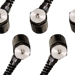
KFH-Rosette Pre-Wired Strain Gauges
KFH-Rosette series offers pre-wired strain gauges designed for easy installation and high-accuracy stress analysis. Featuring a planar rosette pattern (0°/45°/90°), these gauges eliminate the alignment errors often associated with stacked designs, ensuring reliable biaxial strain readings.
- Pre-wired leads (two 1 m or three 3 m per grid) simplify setup—no soldering required at the measuring point
- Optimized for steel structures, providing accurate temperature compensation
- Sold in convenient packs of ten, ideal for multi-point strain mapping or laboratory testing
The KFH-Rosette strain gauge is a dependable choice for structural testing, component validation, and research applications where biaxial stress direction must be resolved accurately and efficiently.
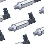
SGT-Full-Bridge-Diaphragm Strain Gauges
SGT-Full-Bridge-Diaphragm strain gauges deliver transducer-quality performance for both bending and axial strain measurement applications. Engineered for demanding environments, these gauges combine precision, ruggedness, and long-term stability in a compact design.
- Full-bridge configuration supports highly accurate static and dynamic measurements
- Etched constantan foil sensing element ensures consistent performance and sensitivity
- Polyimide carrier medium provides excellent flexibility, a small bending radius, and long-term sealing for enhanced durability
- Operates reliably across a broad temperature range, making it suitable for diverse industrial and research applications
- Sold in packs of five for convenient multi-point testing or transducer fabrication
The SGT-Full-Bridge-Diaphragm series is ideal for precision transducer design, pressure and load measurement, and dynamic structural testing, where both accuracy and environmental resistance are critical.
SGK-2-ELEMENT90 T-Rosette Strain Gauges
SGK-2-ELEMENT90 strain gauges from the OMEGADYNE® K-Series deliver transducer-quality performance and exceptional stability across a wide temperature range of –75 to 200°C (–100 to 392°F). Constructed with Karma alloy, these T-rosette gauges maintain excellent linearity, fatigue life, and thermal stability, making them ideal for long-term, high-accuracy measurements.
- Karma alloy grids ensure high thermal resistance and consistent output under variable environmental conditions
- Plated solder pads simplify installation—no special solders or fluxes required
- Available in multiple T-rosette configurations for axial strain and column load cell applications
- Good fatigue performance and long-term stability, suitable for both static and dynamic testing
- Custom gauges available with fast delivery for specialized transducer or R&D applications
The SGK-2-ELEMENT90 series is an excellent choice for industrial load and force transducers, column strain measurement, and temperature-sensitive environments requiring both accuracy and resilience.

Accelerometer: What is it & How it Works | Omega What is an Accelerometer?
Custom Pressure Transducers, all you need to know Introduction to Pressure Transducers Manufacturing