Getting a load cell installation right is key to making sure your measurements stay accurate and consistent over time. While load cells come in many shapes and sizes, most installations benefit from the same set of best practices. When these fundamentals are in place, you’ll get better data, longer sensor life, and a weighing system your application can rely on.
Load Alignment and Force Direction
For any load cell to deliver accurate readings, the force must be applied exactly as the manufacturer intended—usually along a single axis. Misalignment is one of the most common sources of load cell error. When force isn’t applied along the correct axis, it introduces side loads or uneven stress that the sensor wasn’t designed to handle. This is especially problematic in dynamic or high-vibration environments, where shifting loads or repeated impact can amplify these errors over time—leading to signal instability, mechanical fatigue, and eventual failure.
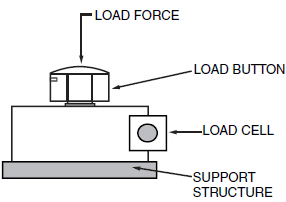
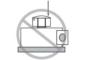
- Apply force directly in line with the load cell’s rated direction
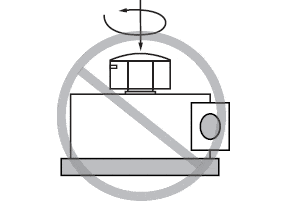
- Avoid bending, side-loading, or twisting (torsional) forces
- Use mechanical guides or fixtures to keep the load centered and stable
Mounting and Structural Support
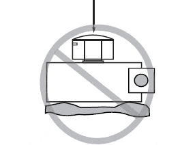
Even with perfect load alignment, poor mounting can lead to uneven force transfer, signal instability, and premature failure. The mounting surface and support structure must be mechanically sound and designed to carry the full expected load without deflection or deformation.
Mounting best practices:
- Use a rigid, flat base plate that evenly distributes the load across the sensor
- Reinforce support structures as needed to prevent movement or sagging
- Ensure the mounting surface is clean, level, and properly aligned before installation
- Avoid soft or flexible materials in the load path—they can absorb force and reduce accuracy
Considerations Before Installation
Before installing a load cell, it’s important to evaluate the conditions that will affect both performance and long-term reliability. The following factors should be reviewed during system planning and site preparation.
Load Orientation
Incorrect load direction is one of the most common sources of measurement error. Load cells are designed to sense force along a specific axis—typically vertical. Any off-axis force, whether from improper mounting or uneven loading, introduces errors and can damage the sensor.
Environmental Factors
Electromagnetic interference, temperature fluctuations, and moisture can all impact signal quality and stability.
- Use shielded cables and EMC-protected enclosures to guard against electrical noise
- Avoid multiple grounding points, which can create ground loops and signal distortion
- Use elastomeric isolation if the load cell is exposed to vibration or thermal expansion from nearby equipment or tanks
Support Structure and Mounting Surface
 Flat and Clean Surface Required
The structural framework must be strong and stable enough to transfer load accurately.
- Use a rigid base plate with a flat, even surface
- Reinforce the structure if necessary to avoid deflection under load
- Ensure the mounting surface is clean, level, and free from debris
Cable Routing and Protection
Improper cabling is a common cause of signal issues and premature failure.
- Use low-capacitance, shielded cables (such as HBM-grade) to maintain signal integrity
- Run cables through steel conduit when possible to prevent mechanical damage
- Keep cables away from motors, transformers, and contactors to minimize electromagnetic interference
How to Connect Four Load Cells
In many industrial and platform-scale applications, multiple load cells are used together to support and measure distributed loads. A common setup involves four load cells—typically placed at each corner of a platform—to evenly measure weight.
Wiring Configuration
Each load cell is wired to a summing box, where the signals are combined and trimmed to produce a single, balanced output.
- The output terminals of all four load cells connect to the summing box
- The summing box compensates for small mechanical differences between cells, such as height or placement, to maintain system accuracy
- The final signal from the summing box is then sent to an indicator, display, or data acquisition system for measurement
How to Test and Verify a Load Cell
If a load cell is giving unexpected readings —or you just want to confirm it’s working properly—there are a few simple tests that can help you verify both its mechanical integrity and electrical performance.
Visual and Mechanical Inspection
Check for physical issues:
- Confirm the load is applied along the correct axis
- Inspect the mounting surface for levelness and cleanliness
- Look for cable damage, loose connectors, or corrosion
- Make sure there’s no debris or misalignment affecting the load path
Electrical Resistance Tests
- Connect the load cell’s excitation terminals to a stable DC voltage source, and connect the signal (output) terminals to a millivoltmeter or measurement device
- Compare the measured zero balance value to the specification provided in the manufacturer’s calibration certificate
Test Insulation and Bridge Integrity
- Check insulation resistance between the load cell wires and the load cell body. This ensures there is no electrical leakage that could interfere with signal accuracy
- Verify bridge symmetry by measuring the resistance between opposite pairs of wires. The values should be balanced and match the specifications provided by the manufacturer
Proper load cell installation and regular verification are essential to maintaining accuracy, safety, and long-term system performance. While many issues can be prevented by following best practices, even small deviations in mounting, load direction, or signal integrity can lead to costly measurement errors over time. Taking the time to test and confirm proper load cell operation helps protect your equipment—and your results.
Connect with a DwyerOmega Expert Today!

Accelerometer: What is it & How it Works | Omega What is an Accelerometer?
Custom Pressure Transducers, all you need to know Introduction to Pressure Transducers Manufacturing