Need assistance? Call us: 1-800-663-4209
OME-DB-24R-24RD
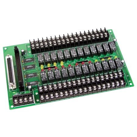
24-Channel Relay Output Board - Panel Mount
Carte de sortie relais 24 canaux - Montage sur panneau
Models In Stock
- 24 Form C SPDT Relays
- OPTO-22 Compatible Connector
- Connects Directly to OME-DIO-24, OME-DIO-48, OME-DIO-144 or Other OPTO-22 Compatible Digital Output Board
- Switch up to 0.5A at 120 Vac Switch up to 1A at 24 Vdc
OME-DB-24R-24RD
From
C$
721.30
Models In Stock
Product Overview
- Control Output 24 Form C SPDT
- Cycle Time 6 ms
- Electrical Life 2 x 10^5 cycles
- Height 132 mm
- Logic TTL Relay On
- Mechanical Life 2 x 10^7 cycles
- Number of Channels 24
- Operating Temperature, Max 60 °C
- Operating Temperature, Min 0 °C
- Power Consumption +12 V @ 528 mA ; +5 V @ 150 mA
- Relative Humidity 5 to 90 % RH non-condensing
- Relay Current 1 A
- Series ID OME-DB-24R-24RD
- Storage Temperature, Max 70 °C
- Storage Temperature, Min -20 °C
- Switching Voltage 120/60 Vac/Vdc
- Voltage Source 0.5 A/120 Vac, 1 A /24 Vdc
- Width 225 mm
L'OME-DB-24R se compose de 24 relais électromécaniques de forme C pour une commutation efficace de la charge par commande programmée. Le contact de chaque relais peut contrôler une charge de 0,5 A / 110 V ou 1 A / 24 Vcc. Le relais est alimenté en appliquant un signal de 5 V au canal de relais approprié sur le connecteur compatible OPTO-22 à 50 broches ou le connecteur D-Sub à 37 broches. Vingt-quatre voyants LED, un pour chaque relais, s'allument lorsque le relais associé est activé. Pour éviter de surcharger l'alimentation électrique de votre PC, cette carte nécessite une alimentation externe de +12 Vcc ou +24 Vcc.
PDFs & Manuals
Show Ratings & Reviews
On page 26 of the manual, the numbering on the right side of the 37-pin D-sub connector seems non-standard. Should standard D-sub numbering (1-19, bottom to top) be used?
Thank you for your question. We will require more information to help on this question, please email the DAS team at DAS@OMEGA.COM”
Date published: 2021-09-30
The manual doesn't provide mounting hole spacing, only outer board dimensions. Can you provide the hole spacing since there are no CAD models?
Thank you for your questions. Diameter is 4mm for the holes. Spacing is 210mm and 122mm.
Date published: 2024-05-21
Do you offer a ACAD download of the 24-Channel Relay Output Board?
Thank you for your question. We do not provide a Cad drawing just dimensions in the manual you can download from the website.
Date published: 2021-02-05
Does this board require an external 5V power supply in addition to 12/24V? I am unsure if the +5V lines shown on page 26 of the manual are for supply or reference.
Hello
Regarding your question, if you are referring to the +5VDC on the board, that is to specifically power up the relays on the board, whereas the 12VDC/24VDC connection is to power up the board itself.
Date published: 2021-10-05