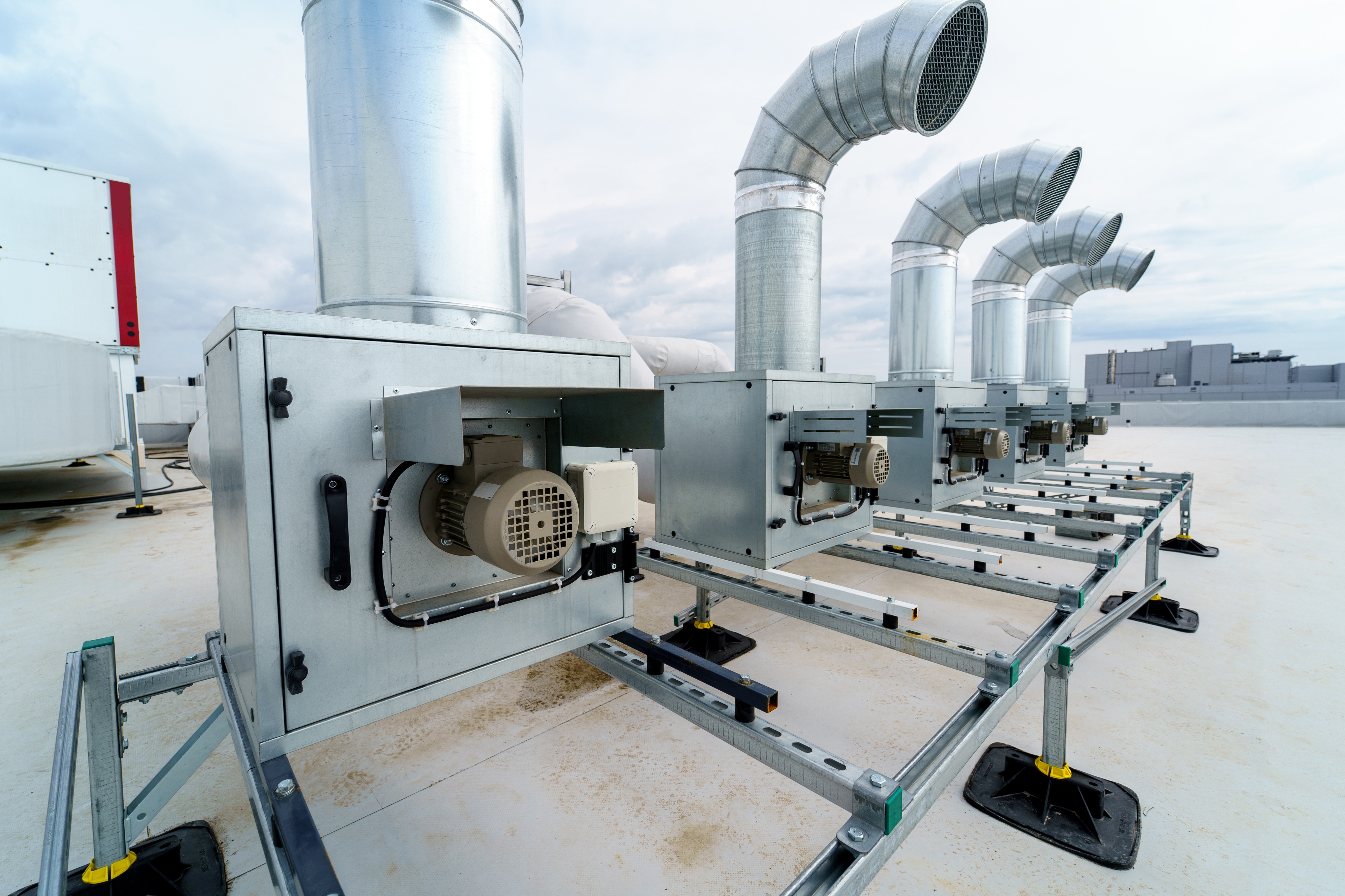
Accurate airflow measurement is crucial for many different applications. From balancing HVAC systems to certifying cleanrooms, even minor inaccuracies can lead to inefficiencies, compliance failures, or equipment issues.
At a basic level, calculating airflow is simple: it involves multiplying the cross-sectional area of the duct by the average velocity of the air. However, collecting that average velocity accurately and consistently across a duct’s surface is a much more challenging task.
Mechanical anemometers have long been a reliable choice for measuring air velocity, offering simplicity and durability in many field applications. However, modern microprocessor-based models build on that foundation by providing faster data collection, improved precision, and enhanced user features that reduce fatigue and increase repeatability.
Understanding Instrument Accuracy
Accurate airflow measurement comes down to two things:
- Using the right airflow measurement device
- Knowing where and how to take readings that reflect real conditions inside the duct
Airflow Isn’t Uniform—And That Matters
When air flows through a duct, its velocity isn’t uniform. Due to friction between the air and the inner surface of the duct, air moves more slowly near the walls and faster in the center. This creates a velocity profile that varies with:
- Duct shape (round, square, or rectangular)
- Flow conditions (laminar vs. turbulent)
- Internal pressure and resistance
To calculate true airflow, a statistically valid sampling of velocities across the duct’s cross section is required.
Measuring Air Flow in Round Ducts
In circular ducts, the most effective strategy is to divide the cross section into equal pie-shaped wedges using evenly spaced diameters, known as traverses.
Three-Diameter Approach
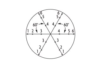
Three-Diameter Approach
For round ducts, the preferred method involves taking velocity readings along three traverses—diameters evenly spaced at 60 degrees apart. Along each radius, three measurements are recorded: one at the outer edge of the duct, one one-third of the way toward the center, and another two-thirds of the way toward the center, resulting in a total of eighteen readings. By concentrating measurements near the perimeter, where friction has the greatest effect on airflow, this method ensures a more accurate representation of the overall velocity profile across the duct.
Alternate Method
When only two traverses are possible—typically spaced 90 ° apart—five velocity readings are taken along each radius. Four are evenly spaced from the duct wall to the center, and one is placed two-thirds of the way in. This 20-point method is slightly less accurate than the preferred three-diameter approach but remains effective for most field applications.
Measuring Airflow in Rectangular or Square Ducts
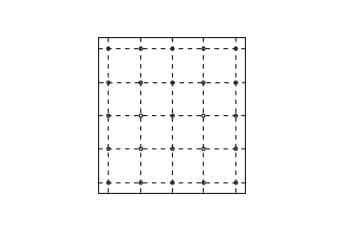
25-Point Approach
Rectangular and square ducts require more sampling points than round ducts due to their larger perimeter surface area and more complex velocity distribution. Depending on duct size, the number of traverses can range from five to seven: five for ducts under 30 inches wide, six for those between 30 and 36 inches, and seven for ducts wider than 36 inches. In total, between twenty-five and forty-nine readings are generally taken.
To achieve high accuracy, the traverse grid should prioritize the slower-moving air near the duct walls. About 64 % of the data points should be placed within approximately 7 % of the distance from the wall, with the remaining points spread across the interior. This distribution ensures that the velocity profile is properly captured, particularly in areas of rapid air deceleration near the perimeter.
Interestingly, while rectangular ducts require heavier sampling near the edges, only about 33 % of the data points in round duct traverses fall near the walls—highlighting the aerodynamic efficiency of circular ductwork, even if it’s not always the most practical design choice.
How to Measure Cross-Sectional Area
To calculate airflow, multiply the average velocity (V) by the duct's cross-sectional area (A):
Accurately determining A depends on the shape of the duct. Use the appropriate formula below:
| Duct Shape | Formula | Variables |
|---|---|---|
| Round Duct |
D = Internal Diameter A = Area (in2 or m2) |
|
| Rectangular / Square Duct |
W = Internal Width H = Internal Height A = Area (in2 or m2) |
Remember the Grille!
Before finalizing your calculation, ask yourself: is there a grille present at the measurement point?
Grilles restrict and disperse airflow, affecting the effective cross-sectional area used in flow rate calculations. To compensate, you must apply a correction factor based on grille type:
| Grille Type | Correction Factor |
|---|---|
| None (open duct) | 1.00 (no change) |
| Square-Punched Grille | 0.88 |
| Bar Grille | 0.78 |
| Steel Strip Grille | 0.73 |
Calculating the Final Flow Rate
Once you’ve collected velocity readings using the correct traverse method, follow these steps to calculate airflow:
- Calculate the average velocity
Use your recorded velocity values to find the mean average across all data points. - Determine the effective cross-sectional area
Use the appropriate formula for round or rectangular ducts. If airflow is measured through a grille or diffuser, adjust the area to account for the free area ratio. - Multiply the average velocity by the effective area using the equation:
Q is the volumetric flow rate, typically expressed in CFM (cubic feet per minute) or m³/hr (cubic meters per hour). - Simultaneous display of air velocity and temperature
- High accuracy (±1.5 % of full scale) for demanding applications
- Analog output options (4–20 mA or 0–10 V) for system integration
- Multiple probe configurations to suit various installation geometries
- Minimum, maximum, and average readings
- Data hold for point-by-point inspection
- RS-232 interface for PC connectivity and uploading up to 99 stored readings from pre-edited files
- A detachable vane probe for easy replacement or upgrade to a miniature probe
- A hard carrying case, batteries, interface cable, software CD, and instruction manual
Streamlining Measurements with DwyerOmega
Once you’ve mastered velocity traversing and accurate area measurement, the next step is choosing the right tools to not only provide accurate, consistent results, but solutions that will simplify the process.
DwyerOmega offers precision airflow instruments designed specifically for professionals who need dependable, field-ready performance. Whether you're balancing a system, validating airflow for compliance, or integrating data into a control loop, the right tool makes all the difference.
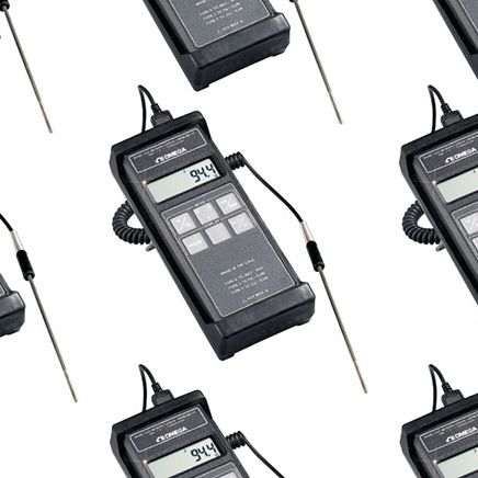
FMA1000 Series Transmitter/Indicator
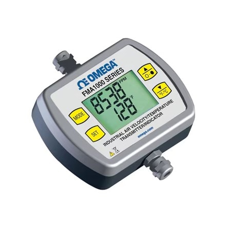
The FMA1000 Series Industrial Air Velocity and Temperature Transmitter/Indicator is ideal for industrial and laboratory environments where airflow accuracy is critical.
Using a three-element RTD design, this instrument is designed to deliver precise measurements. One RTD is dedicated to sensing air temperature, while the other two measure air velocity by detecting the rate of heat loss as they are cooled by moving air. This method, known as thermal anemometry, is a proven and highly accurate technique for capturing real-time airflow.
This setup allows the FMA1000 to deliver fast, reliable readings in HVAC systems, cleanrooms, manufacturing facilities, and R&D test benches.
Key features include:
Model 9671 Multi-Function Vane Thermo-Anemometer
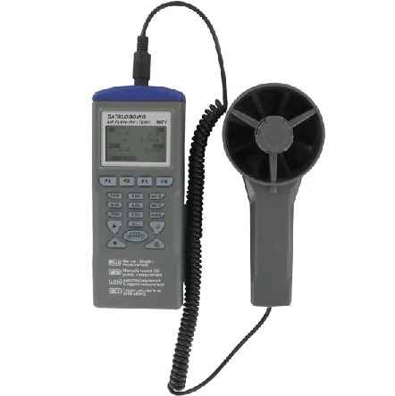
The Model 9671 Multi-Function Vane Thermo-Anemometer is a versatile handheld instrument designed for technicians who need comprehensive environmental data on-site. It's ideal for air balancing, field diagnostics, and HVAC performance verification across a wide range of conditions.
This device provides accurate readings for air velocity and volumetric airflow, with user-selectable units including feet per minute, meters per second, knots, miles per hour, and kilometers per hour. Its large 1.8″ display makes it easy to view real-time values, and it offers essential data functions and additional features including:
Connect with a DwyerOmega Expert Today!

What Is An Anemometer And What Does It Measure? Introduction to Air Velocity Measurement
