Precision matters when it comes to airflow measurement. Applications like cleanroom certification and HVAC balancing depend on accurate data to prevent inefficiencies, regulatory setbacks, and performance issues.
At a basic level, calculating airflow is simple: it involves multiplying the cross-sectional area of the duct by the average velocity of the air. However, collecting that average velocity accurately and consistently across a duct presents a much more challenging task.
Mechanical anemometers have long been a reliable choice for measuring air velocity, offering simplicity and durability in many field applications. Today's devices build on that foundation by providing faster data collection, improved precision, and enhanced user features that reduce fatigue and increase repeatability.
Understanding Instrument Accuracy
Accurate airflow measurement comes down to two things:
- Using the right airflow measurement device
- Knowing where and how to take readings that reflect real conditions inside the duct
Airflow Isn’t Uniform—and That Matters
As air flows through a duct, friction between the air and the duct walls causes the air to move more slowly near the edges and faster in the center. This creates a velocity profile that varies with:
- Duct shape (round, square, or rectangular)
- Flow conditions (laminar vs. turbulent)
- Internal pressure and resistance
To calculate true airflow, a statistically valid sampling of velocities across the duct’s cross section is required.
Measuring Airflow in Round Ducts
Log-Linear Traverse Method
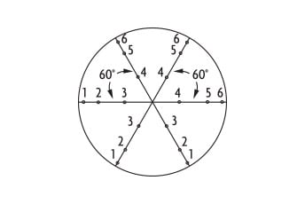
In circular ducts, the most effective strategy is to divide the cross section into equal pie-shaped wedges using evenly spaced diameters, known as traverses.
Three-Traverse Approach
Along each radius—which are spaced 60° apart—three measurements are recorded: one at the outer edge of the duct, one one-third of the way toward the center, and another two-thirds of the way toward the center, resulting in a total of eighteen readings. By concentrating measurements near the perimeter, where friction has the greatest effect on airflow, this method ensures a more accurate representation of the overall velocity profile across the duct.
Alternate Method
When only two traverses are possible—typically spaced 90° apart—five velocity readings are taken along each radius. Four are evenly spaced from the duct wall to the center, and one is placed two-thirds of the way in. This 20-point method is slightly less accurate than the preferred three-diameter approach but remains effective for most field applications.
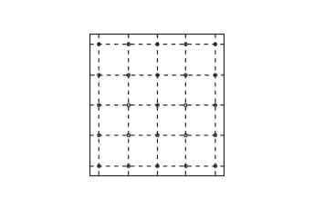
Traverse Grid
Measuring Airflow in Rectangular or Square Ducts
Rectangular and square ducts require more sampling points than round ducts due to their larger perimeter surface area and more complex velocity distribution. Depending on duct size, the number of traverses can range from five to seven: five for ducts under 76.2 cm (30 in) wide, six for those between 76.2 cm and 91.44 cm (30 in and 36 in), and seven for ducts wider than 91.44 cm (36 in). In total, between twenty-five and forty-nine readings are generally taken.
To achieve high accuracy, the traverse grid should prioritize the slower-moving air near the duct walls. About 64% of the data points should be placed within approximately 7% of the distance from the wall, with the remaining points spread across the interior. This distribution ensures that the velocity profile is properly captured, particularly in areas of rapid air deceleration near the perimeter.
How to Measure Cross-Sectional Area
To calculate airflow, multiply the average velocity (V) by the duct's cross-sectional area (A):
Accurately determining A depends on the shape of the duct. Use the appropriate formula below:
| Duct Shape | Formula | Variables |
|---|---|---|
| Round Duct |
D = Internal Diameter A = Area (in2 or m2) |
|
| Rectangular / Square Duct |
W = Internal Width H = Internal Height A = Area (in2 or m2) |
Remember the Grille!
Before finalizing your calculation, ask yourself: is there a grille present at the measurement point?
Grilles restrict and disperse airflow, affecting the effective cross-sectional area used in flow rate calculations. To compensate, you must apply a correction factor based on grille type.
| Grille Type | Correction Factor |
|---|---|
| None (open duct) | 1.00 (no change) |
| Square-Punched Grille | 0.88 |
| Bar Grille | 0.78 |
| Steel Strip Grille | 0.73 |
Calculating the Final Flow Rate
Once you’ve collected velocity readings using the correct traverse method, follow these steps to calculate airflow:
- Calculate the average velocity
Use your recorded velocity values to find the mean average across all data points. - Determine the effective cross-sectional area
Use the appropriate formula for round or rectangular ducts. If airflow is measured through a grille or diffuser, adjust the area to account for the free area ratio. - Multiply the average velocity by the effective area using the equation:
Q is the volumetric flow rate, typically expressed in CFM (cubic feet per minute) or m³/hr (cubic meters per hour). - Sensing elements have been coated with an engineered conformal coating to ensure durability and longevity
- Field selectable ranges can be quickly configured without power to the unit
- Optional integral display or portable remote display tool
- Optional BACnet MS/TP or Modbus® RTU/ASCII communication protocol allows units to be daisy-chained while providing access to all of the velocity and flow data
- Compatible with Dwyer RP1 thermo-hygrometer and VP1 100 mm vane thermo-anemometer probes
- Visible in any condition due to high contrast and backlit LCD display
- Able to store up to 99 readings
- Probe sensors are protected by the integral sliding cover
Streamlining Measurements with DwyerOmega
Once you’ve mastered velocity traversing and accurate area measurement, the next step is choosing the right tools to not only provide accurate, consistent results, but solutions that will simplify the process.
DwyerOmega offers precision airflow instruments designed specifically for professionals who need dependable, field-ready performance. Whether you're balancing a system, validating airflow for compliance, or integrating data into a control loop, the right tool makes all the difference.
AVUL Series Air Velocity Transmitters
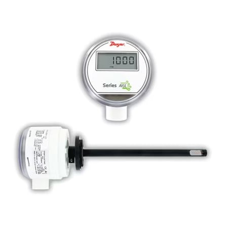
AVUL Air Velocity Transmitters are ideal for VAV systems, which are types of HVAC systems that regulate temperature by varying the amount of conditioned air that is delivered to different zones of a building and are capable of quickly and accurately measuring air velocity or volumetric flow in imperial or metric units.
Simultaneous current and voltage outputs on all models provide universal inputs to monitoring equipment while the output range, units, and 0 to 5/10 VDC, 4-20 mA output can be configured via local DIP switches. Models are available in 3% and 5% of reading accuracy models to suit a variety of needs.
Key Features Include:
Model-471B Dual Function Thermo-Anemometer
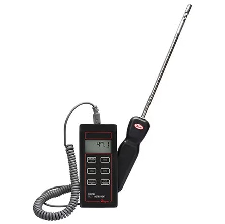
The Model-471B Dual Function Thermo-Anemometer is a versatile dual function unit that quickly and easily measures air velocity or volumetric flow as well as air temperature in imperial or metric units. A stainless steel probe is included, which has a comfortable hand grip and etched insertion depth marks. The extruded aluminum housing fully protects electronics, yet is lightweight and comfortable to hold.
Key Features Include:
Connect with a DwyerOmega Expert Today!

What Is An Anemometer And What Does It Measure? Introduction to Air Velocity Measurement
