Skip to search Skip to main content Skip to navigation

Need assistance? Call us: 1-800-663-4209

We noticed you are in , please visit your local site by clicking the below link for regional offers and support.

Series-391-393-394Configuration

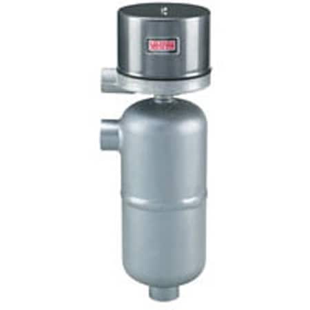
Weatherproof Level Control, Stainless Steel, 650 psig, 600 °F, for Refineries

  • Heavy-duty welded chamber rated 650 psi @ 600 °F, ideal for refinery and process-vessel use
  • Stainless-steel float and gravity-return switch design for long, reliable service life
  • Weatherproof or explosion-proof housings (NEMA 4X / Class I-II) suit harsh environments
  • Handles fluids to ~0.70 specific gravity; flanged or NPT models for flexible installation

Series-391-393-394

Build your Part Number

Weatherproof Level Control, Stainless Steel, 650 psig, 600 °F, for Refineries Series-391-393-394 Series-391-393-394
loading all models
Product Overview
  • Series ID Series-391-393-394

Supported Applications

The Dwyer Series 391, 393, and 394 are side-mounted, chamber-sealed liquid level controls designed for heavy-duty industrial applications. These single-stage, non-adjustable switches operate via a magnetic plunger and float mechanism to monitor compatible liquids in process vessels.

Documented use cases include refinery service environments where the series provides weatherproof protection against harsh conditions. The design supports high-pressure and high-temperature liquid level control tasks requiring gravity return action for long life without springs.

Operating Conditions & Performance

The Series 391, 393, and 394 are rated for process temperatures up to 600°F (315.6°C) with an ambient operating temperature of 212°F (100°C). Pressure ratings reach 800 psig (55 bar) at 100°F (37.7°C), reducing to 650 psig (45 bar) at 600°F (315.6°C); higher pressure ratings are available.

Switch operation is defined by specific liquid level changes based on the fluid's Specific Gravity (Sp.Gr.). For a Sp.Gr. of 1.0, dimension A measures 4-3/8" (111mm) and B measures 1" (25.4 mm). At a Sp.Gr. of 0.80, dimension A is 4-11/16" (191 mm) and B is 1-3/16" (12.3 mm).

Temperature limitations for specific switch types require heat fins or high temperature switches when process temperatures exceed the following thresholds: above 500°F (260°C) with mercury switches, above 400°F (204°C) with snap switches, and above 350°F (176.7°C) with hermetically sealed snap switches.

Key Performance Specifications

  • Pressure Rating: 800 psig (55 bar) at 100°F (37.7°C); 650 psig (45 bar) at 600°F (315.6°C)
  • Process Temperature: Up to 600°F (315.6°C)
  • Ambient Temperature: 212°F (100°C)
  • Enclosure Rating: NEMA 4X standard; optional general purpose or explosion-proof enclosures
  • Weight: 10 lb (4.5 kg)

Configuration Options

The series offers configurable options across switch types, materials of construction, and process connections to accommodate diverse installation requirements.

Switch Types & Electrical Output

  • SPDT Mercury: Model 391-WT-4810-C1-80
  • SPDT Snap Switch: Model 391-WT-7810-C1-80 (hermetically sealed snap switch option available)
  • SPDT Hermetically Sealed Snap: Model 391-WT-7810HM-C1-80
  • Electrical Connection: Screw terminal with a standard 3/4" female NPT conduit connection (rotatable 360°)

Materials & Construction

  • Body Material: Carbon steel welded chamber; stainless steel bodies available for specific controls where dimensions A, B, and C may vary.
  • Float and Trim Materials: 303 SS, 304 SS, 316 SS, and 430 SS
  • Housing Options: Weatherproof (standard), General Purpose ('G'), or Explosion-Proof ('E')

Process Connections

  • Standard Connection: 1" female NPT
  • Optional Connections: 1" socket weld hub or flange connections

Key Product Differences

The Series 391, 393, and 394 differ primarily by switch mechanism type (mercury vs. snap vs. hermetically sealed) and enclosure rating (weatherproof NEMA 4X standard versus optional general purpose or explosion-proof). Model numbers follow the format 391-WT--C1-80, where the model segment identifies the specific switch configuration.

Differences in physical dimensions occur based on fluid Specific Gravity; controls designed for lower Sp.Gr. fluids (e.g., 0.80) exhibit larger dimension A and B values compared to those calibrated for Sp.Gr. 1.0. Additionally, stainless steel body variants may present dimensional variations relative to the standard carbon steel construction.

UL LISTED certification applies to the series; however, UL listing is not applicable on HM (mercury) switch configurations.

  • bvseo_sdk, java_sdk, bvseo-4.0.0
  • CLOUD, getReviews, 4ms
  • REVIEWS, PRODUCT
  • bvseo-msg: The resource to the URL or file is currently unavailable.;
  • bvseo_sdk, java_sdk, bvseo-4.0.0
  • CLOUD, getContent, 19ms
  • QUESTIONS, PRODUCT
  • bvseo-msg: The resource to the URL or file is currently unavailable.;
EXAMPLE 391 WT 7810 C1 70   391-WT-7810-C1-70 Liquid Level Control with welded carbon steel chamber, watertight – NEMA 4X enclosure, SPDT snap action switch rated 12 amp 120 VAC, 5 amp 240 VAC, fixed deadband and automatic reset, operating pressure 600 psig (41 bar) at 100ºF (38ºC), 500 psi (34 bar) at 600ºF (315ºC), side/bottom process connections 1” NPT, minimum specific gravity 0.70.
CONNECTION 391           One Horizontal and One Vertical 1” NPT or Socket Weld
393           One Vertical and One Horizontal Flanged Connection
394           Two Vertical Flanged Connections
ENCLOSURE   G         General purpose, NEMA 1
  WT         Weatherproof, NEMA 3R, 4, 4X
  E         Explosion-proof, NEMA 7, 9, Class I Groups B, C, D, Class II Groups E, F, G
  EV         Explosion-proof, vapor proof, NEMA 7, 9, Class I Groups B, C, D, Class II Groups E, F, G
CIRCUITS
(for electrical circuits,
See charts A & B below)
    48XX       Single stage, mercury switch, see chart A.
    48XX       Two stage, mercury switch, see chart A.
    78XX       Single stage, snap switch, see chart B.
    78XX       Two stage, snap switch, see chart B.
    78XXHM       Hermetically sealed snap switch, see chart B.
    98XX       Single stage, high capacity DC snap switch, see chart B.
    98XX       Two stage, high capacity DC snap switch, see chart B.
    10XX       Single stage, high temperature snap switch, see chart B.
    10XX       Two stage, high temperature snap switch, see chart B.
CHAMBER MATERIAL             Refer to chart C below for pressure/temperature ratings
      C1     Carbon steel body
MINIMUM SPECIFIC
GRAVITY
        70   0.70 specific gravity (391 only)
        80   0.80 specific gravity (391 only)
        95   0.95 specific gravity (391 only)
        170   0.70 specific gravity & 150# flange (393, 394 only)
        180   0.80 specific gravity & 150# flange (393, 394 only)
        195   0.95 specific gravity & 150# flange (393, 394 only)
        370   0.70 specific gravity & 300# flange (393, 394 only)
        380   0.80 specific gravity & 300# flange (393, 394 only)
        395   0.95 specific gravity & 300# flange (393, 394 only)
        670   0.70 specific gravity & 600# flange (393, 394 only)
        680   0.80 specific gravity & 600# flange (393, 394 only)
        695   0.95 specific gravity & 600# flange (393, 394 only)
OPTIONS           H2 1” socket weld hub instead of 1” NPT
          STW SS tag wired
          01 Breather only (E-Housing only)
          02 Drain only (E-Housing only)
          12 Breather and drain (E-Housing only)
          23720 Fungus proofing special 23720
CHARTS A & B - ELECTRICAL CIRCUITS AND RATINGS
SWITCH TYPE
SWITCH ACTION
ELECTRICAL RATINGS IN AMPS
ORDERING CODE


AC
DC
SINGLE STAGE
TWO STAGE
120V
240V
440V
30V
125V
250V
LOWER
UPPER
CHART A
Mercury Contacts
SP-ST open on level FALL
10
5
3†
 
10
5
-4821
-4821
-21
UL
SP-ST open on level RISE
10
5
3†
 
10
5
-4820
-4820
-20
UL
SP-DT one switch
4
2
1†
 
4
2
-4810
-4810
-10
UL
SP-DT two switches E.I.*
10
5
3†
 
10
5
-4815
-4815
-15
UL
DP-ST two switches E.I.* open on level FALL
10
5
3†
 
10
5
-4813
-4813
-13
UL
DP-ST two switches E.I.* open on level RISE
10
5
3†
 
10
5
-4814
-4814
-14
UL
DP-DT two SP-DT switches
4
2
1†
 
4
2
-4806
-4806
-06
UL
CHART B
snap action contacts
SP-DT one switch
12
5
3†
 
0.5**
0.25**
-7810
-7810
-10
UL
DP-DT Two SP-DT switches
12
5
3†
 
0.5**
0.25**
-7806
-7806
-06
UL
SP-DT one hermetically sealed switch
5
5
 
5**
 
 
-7810HM
-7810HM
-10HM
 
DP-DT two hermetically sealed SP-DT switches
5
5
 
5**
 
 
Configure Product
Saved Configuration
View Configuration
Terms and Conditions
Saved Addresses
This field is required
Errors were found with the address you provided. Please verify your address.
Date should be in MM/DD/YYYY format
mm/dd/yy
Date should be in MM/DD/YYYY format
Please enter valid values
Please enter future date
Please enter the shipping date
Shipment date is updated
en-US
en
Save Configuration