Need assistance? Call us: 1-800-663-4209

Series-401Configuration
Liquid Level Controls, 600 psi, 500 °F, 12 ft Depth, Adjustable, Alarm
- Installed via top-flanged mount into tanks/sumps; supports installations to ~12 ft depth
- Rated for up to 600 psi and 500 °F; handles high-pressure and high-temperature fluid environments
- Configurable for single-stage (pump control) or two-stage (alarm/shutdown) operation
- Supports fluids with specific gravities down to ~0.50 and offers mercury or snap-action switch options

Product Overview
- Series ID Series-401
Supported Applications
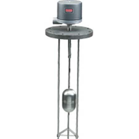
The Dwyer Series 401 Magnetic Liquid Level Controls are top-mounting devices designed for pressurized or non-pressurized tanks and sumps. These heavy-duty controls utilize a magnetically actuated switch mechanism operated by a float to manage high and low liquid levels. The series supports single-stage (Type 401-1) and two-stage operations (Types 401-2, 401-3, 401-4), providing configurations for pump operation combined with high or low alarms, shutdowns, or dual alarm functions.
Operating Conditions & Performance
The Series 401 operates in environments requiring robust pressure and temperature ratings. The series supports process temperatures from -20 to 500°F (-29 to 260°C) with an ambient operating limit of 212°F (100°C). Pressure capabilities vary by float material, offering up to 600 psi at 500°F MAX. for specific stainless steel configurations.
Measurement ranges extend to depths of 12 ft., accommodating fluids with a specific gravity from 0.50 to 1.0. Operating depth limits and guide rod lengths are dependent on the float size, material, and fluid specific gravity; critical dimensions must be verified with the factory before placing an order.
Pressure and Temperature Ratings by Float Type
- 4-1/2" Copper: 150 PSI @ 300°F MAX.
- 4-1/2" 304 S.S.: Available at 300 PSI or 600 PSI, both rated to 500°F MAX.
- 7" 304 S.S.: Ratings include 450 PSI @ 100°F MAX., 425 PSI @ 200°F MAX., and 300 PSI @ 500°F MAX.
- 3-1/2" x 6" S.S.: Available at 300 PSI or 450 PSI, both rated to 100°F MAX.
Configuration Options
The Series 401 is configurable across multiple dimensions including enclosure type, switch mechanism, flange assembly, and float material. The series supports various NEMA ratings depending on the selected housing:
- G (General Purpose): NEMA-1.
- WT (Watertight-Dusttight): Suitable for NEMA 1, 2, 3, 4, and 4X.
- E (Explosion-Proof): NEMA 7, 9; Class I Groups B, C, D; Class II Groups E, F, G, Division I and II. CSA approved for Groups C, D, E, F, G only.
- EV (Vapor Proof-Explosion-Proof): NEMA 7, 9; Class I Groups B, C, D; Class II Groups E, F, G, Division I and II.
Switch options include mercury contacts or snap action contacts with Single Pole Single Throw (SPST), Single Pole Double Throw (SPDT), and Double Pole Double Throw (DPDT) configurations. Electrical ratings for AC circuits cover 120V, 240V, and 440V; DC ratings cover 30V, 125V, and 250V.
Flange and Guide Rod Configurations
The series offers flanges in Cast Iron (CI) or Carbon Steel (CS) with pressure classes of 125# or 150#. Flange sizes include 4", 5", 6", and 8". Guide rods are available in Brass or 303SS, with lengths up to 12 ft.
Key Product Differences
The Series 401 distinguishes itself through specific construction types that define the control logic:
- Type 401-1 (Single Stage): Lower stage has adjustable deadband; upper stage has fixed deadband. Typically used for pump operation and high alarm or shutdown.
- Type 401-2 (Two Stage): Lower stage has adjustable deadband; upper stage has fixed deadband. Used for pump operation with high alarm/shutdown.
- Type 401-3 (Two Stage): Upper stage has adjustable deadband; lower stage has fixed deadband. Used for pump operation and low alarm or shutdown.
- Type 401-4 (Two Stage): Each stage has a fixed deadband with an adjustable deadband between stages. Typically used for high/low alarms or shutdowns, including high-high or low-low scenarios.
Circuit specifications vary by switch type and action. Mercury contact switches are identified by codes starting with 48 (e.g., -4820), while snap action contacts use codes such as 78XX for standard applications and 98XX for high-capacity DC applications requiring heat fins if process temperature exceeds 350°F.
PDFs & Manuals
Show Ratings & Reviews
| EXAMPLE | 401 | 1 | G | 4810 | B | 1.0 | 40 | 1 | STW | 401-1-G-4810-B-1.0-40-1-STW Top mount Float Type Level Control, NEMA 1 enclosure, Single Stage, adjustable deadband, 3-1/2" x 6" 304SS float, 303SS rod, 316SS stop, 1.0 specific gravity, operating point 40", 5" 125# CI flange, 3-1/2" x 6"float, 4' brass guide rods, with SS tag wired. |
| SERIES | 401 | Top Mount Float Type Level Control | ||||||||
| CONSTRUCTION | 1 | Single stage with adjustable deadband | ||||||||
| 2 | Two stage, lower stage has adjustable deadband., upper stage has fixed deadband | |||||||||
| 3 | Two stage, upper stage has adjustable deadband, lower stage has fixed deadband | |||||||||
| 4 | Two stage, each stage has fixed deadband with adjustable deadband between stages | |||||||||
| ENCLOSURE | G | General Purpose, NEMA 1 | ||||||||
| WT | Weather tight, NEMA 1, 2, 3, 4, 4X | |||||||||
| E | Explosion-proof, NEMA 7, 9, Class I Groups B, C, D, Class II Groups E, F, G, Div. I & II; CSA approved Groups C, D, E, F, G only | |||||||||
| EV | Explosion-proof/Vapor-proof, NEMA 7, 9, Class I Groups B, C, D, Class II Groups E, F, G, Div. I & II | |||||||||
| CIRCUITS | 48XX | Single Stage Mercury Switch, see chart D | ||||||||
| 48XX-XX | Two Stage, Mercury Switch, see chart D | |||||||||
| 78XX | Single Stage, Snap Switch, see chart D | |||||||||
| 78XX-XX | Two Stage, Snap Switch, see chart E | |||||||||
| 78XXHM | Hermetically Sealed Snap Switch, see chart E | |||||||||
| 98XX | Single Stage, High Capacity DC Snap Switch, use heat fins (HF) if process temperature exceeds 350°F (177°C), do not exceed 450°F (232°C), see chart E | |||||||||
| 98XX-XX | Two Stage, High Capacity DC Snap Switch, use heat fins (HF) if process temperature exceeds 350°F (177°C), do not exceed 450°F (232°C), see chart E | |||||||||
| FLOAT, ROD AND STOP MATERIAL |
0 | No Float | ||||||||
| B | 3-1/2" x 6" 304SS Float, 303SS Rod, 316SS Stop | |||||||||
| C | 4-1/2" Copper Float, 303SS Rod, Brass Stop | |||||||||
| D | 4-1/2" 316SS Float, 303SS Rod, 316SS Stop | |||||||||
| E | 7" 304SS Float, 303SS Rod, 316SS Stop | |||||||||
| SPECIFIC GRAVITY |
0 | No Float, No Specific Gravity | ||||||||
| 1.0 | 1.0 Specific Gravity | |||||||||
| 0.72 | 0.72 Specific Gravity | |||||||||
| 0.62 | 0.62 Specific Gravity | |||||||||
| 0.50 | 0.50 Specific Gravity | |||||||||
| OPERATING POINT |
0 | No Float Road | ||||||||
| XX | Operating Point from 13 to 140 Inches | |||||||||
| FLANGE AND GUIDE RODS |
0 | No Flange, No Guide Rods | ||||||||
| 7 | 5" 150# CS Flange, 3-1/2" x 6" Float, 4' Brass Guide Rods | |||||||||
| 8 | 5" 150# CS Flange, 3-1/2" x 6" Float, 8' Brass Guide Rods | |||||||||
| 9 | 5" 150# CS Flange, 3-1/2" x 6" Float, 12' Brass Guide Rods | |||||||||
| 10 | 5" 150# CS Flange, 3-1/2" x 6" Float, 4' 303SS Guide Rods | |||||||||
| 11 | 5" 150# CS Flange, 3-1/2" x 6" Float, 8' 303SS Guide Rods | |||||||||
| 12 | 5" 150# CS Flange, 3-1/2" x 6" Float, 12' 303SS Guide Rods | |||||||||
| 19 | 6" 150# CS Flange, 3-1/2" x 6" Float, 4' Brass Guide Rods | |||||||||
| 20 | 6" 150# CS Flange, 3-1/2" x 6" Float, 8' Brass Guide Rods | |||||||||
| 21 | 6" 150# CS Flange, 3-1/2" x 6" Float, 12' Brass Guide Rods | |||||||||
| 22 | 6" 150# CS Flange, 3-1/2" x 6" Float, 4' 303SS Guide Rods | |||||||||
| 23 | 6" 150# CS Flange, 3-1/2" x 6" Float, 8' 303SS Guide Rods | |||||||||
| 24 | 6" 150# CS Flange, 3-1/2" x 6" Float, 12' 303SS Guide Rods | |||||||||
| 31 | 6" 150# CS Flange, 4-1/2" Float, 4' Brass Guide Rods | |||||||||
| 32 | 6" 150# CS Flange, 4-1/2" Float, 8' Brass Guide Rods | |||||||||
| 33 | 6" 150# CS Flange, 4-1/2" Float, 12' Brass Guide Rods | |||||||||
| 34 | 6" 150# CS Flange, 4-1/2" Float, 4' 303SS Guide Rods | |||||||||
| 35 | 6" 150# CS Flange, 4-1/2" Float, 8' 303SS Guide Rods | |||||||||
| 36 | 6" 150# CS Flange, 4-1/2" Float, 12' 303SS Guide Rods | |||||||||
| 64 | 6" 300# CS Flange, 4-1/2" Float, 4' 303SS Guide Rods | |||||||||
| 65 | 6" 300# CS Flange, 4-1/2" Float, 8' 303SS Guide Rods | |||||||||
| 43 | 8" 150# CS Flange, 7" Float, 4' Brass Guide Rods | |||||||||
| 44 | 8" 150# CS Flange, 7" Float, 8' Brass Guide Rods | |||||||||
| 45 | 8" 150# CS Flange, 7" Float, 12' Brass Guide Rods | |||||||||
| 46 | 8" 150# CS Flange, 7" Float, 4' 303SS Guide Rods | |||||||||
| 47 | 8" 150# CS Flange, 7" Float, 8' 303SS Guide Rods | |||||||||
| 48 | 8" 150# CS Flange, 7" Float, 12' 303SS Guide Rods | |||||||||
| OPTIONS | STW | SS Tag Wired | ||||||||
| 01 | Breather Only (E-Housing only) | |||||||||
| 02 | Drain Only (E-Housing only) | |||||||||
| 12 | Breather and Drain (E-Housing only) | |||||||||
| 14210.40 | Spec. 14210 for Sch 40 | |||||||||
| 14210.80 | Spec. 14210 for Sch 80 | |||||||||
| 23720 | Fungus Proofing |
CHART B - FLOAT, FLOAT ROD AND STOPS
|
CODE
|
SIZE
|
MATERIAL
|
PRESS/TEMP MAX
|
ROD
|
STOPS
|
|
A
|
3-1/2" X 6" (89 X 152.4 mm)
|
304SS Float
|
300 psi (21 bar)/500°F (260°C)
|
303SS
|
Brass
|
|
B
|
3-1/2" X 6" (89 X 152.4 mm)
|
304SS Float
|
300 psi (21 bar)/500°F (260°C)
|
303SS
|
316SS
|
|
C
|
4-1/2" (114 mm)
|
Copper Float
|
150 psi (10 bar)/300°F (149°C)
|
303SS
|
Brass
|
|
D
|
4-1/2" (114 mm)
|
316SS Float
|
300 psi (21 bar)/500°F (260°C)
|
303SS
|
316SS
|
|
E
|
7" (178 mm)
|
304SS Float
|
300 psi (21 bar)/500°F (260°C)
|
303SS
|
316SS
|
CHART C - FLANGE & GUIDE ROD ASSEMBLY