Need assistance? Call us: 1-800-663-4209



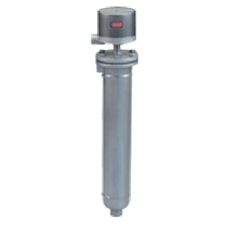
Series-225-227-228Configuration
Flanged Deadband Level Control for Oil & Chemical Plants – 12-48 in Adjustments
- Heavy-duty flanged chamber supports pressures up to ~1000 psi and temps to ~475 °F
- Adjustable dead-band increments (12″, 24″, 36″, 48″) for flexible pump control or alarm staging
- Configurable for single-stage or two-stage operation (pump + high or low alarm/shutdown)
- Side-mount design, minimum specific gravity ~0.75, with flanged or socket-weld process connections


Product Overview
- Series ID Series-225-227-228
Supported Applications
The Dwyer Series 215, 225, 217, 227, and 218, 228 Liquid Level Controls are designed for liquid level control in industrial applications. These controls incorporate magnetically actuated switch mechanisms operated by a magnetic armature placed into or out of the magnetic field of the switch magnet via float action. Documented application areas include oil refineries, chemical plants, power stations, pumping stations, heat transfer systems, sanitary and waste water facilities, drip legs, hydraulic systems, and boilers.
Operating Conditions & Performance
The series features an adjustable deadband ranging from 12" (305 mm) to 24" (610 mm). Process temperature ratings extend up to 475°F (246°C), with ambient operating temperatures rated to 212°F (100°C). Pressure capabilities vary by type and specific gravity, reaching up to 1000 psig (68.9 bar) at 100°F for Series 225 configurations.
Minimum specific gravity requirements are defined as follows:
- Series 215, 217, 218: Minimum Specific Gravity 0.6
- Series 225, 227, 228 (Standard): Minimum Specific Gravity 0.75
- Series 225, 227, 228 (High Pressure/Specific Configurations): Minimum Specific Gravity 0.80
Pressure ratings at specific temperatures include:
- Type 215: 450 psi at 100°F; 300 psi at 500°F
- Type 217: 275 psi at 100°F; 150 psi at 500°F
- Type 218: 450 psi at 100°F; 300 psi at 500°F
- Type 225 (SG .75): 600 psi at 100°F; 550 psi at 475°F
- Type 225 (SG .80): 1000 psi at 100°F; 850 psi at 475°F
- Type 227 (SG .75, Flange Class 600): 600 psi at 100°F; 500 psi at 475°F
- Type 228 (SG .80, Flange Class 600): 1000 psi at 100°F; 750 psi at 475°F
Warnings note that cold shock or water hammer must be avoided to prevent damage to the float and ensure proper operation.
Configuration Options
The series supports multiple enclosure types, process connections, switch configurations, and materials of construction. Model numbers follow the format: TYPE <SERIES>-<ENCLOSURE>-<CIRCUIT>-<MATERIAL>-<PRESSURE_RATING>.
Enclosures
- G: General Purpose (Weatherproof NEMA-3R, 4, 4X); painted steel and aluminum.
- WT: Water tight; painted steel, aluminum, neoprene. Explosion-proof NEMA-7, 9 for Class I Groups B, C, D and Class II Groups E, F, G.
- E: Explosion Proof (NEMA-7, 9); aluminum.
- EV: Vapor Proof - Explosion Proof; aluminum and neoprene. Single stage mercury switch configurations available.
Process Connections & Chamber Construction
- Series 215, 225 (NPT): Standard 1" NPT pipe connection; optional 1" socket weld hub (H2 option).
- Series 217, 227: Flange Vertical and Horizontal 1" R.F. Forged Steel.
- Series 218, 228: Both Flanges Vertical 1" R.F. Forged Steel.
Chamber construction codes (e.g., C1-75, C1-680) define specific gravity requirements and flange classes ranging from 150# to 600#. Side/bottom or side/side process connections are available depending on the code.
Switch Types & Electrical Ratings
The series offers Mercury Contacts (Chart A) and Snap-Action Contacts (Chart B), including hermetically sealed options. Switch actions include SP-ST, SP-DT, DP-ST, and DP-DT configurations with electrical ratings in AMPS varying by voltage.
- Mercury Contacts: Ratings up to 10A AC / 5A DC for specific switch types (e.g., -4820, -4821).
- Snap-Action Contacts: Ratings include 12A at 125VDC and 5A at 250VDC for standard snap switches (-78XX); high capacity DC options available.
A 3/4" NPT conduit connection is provided on all types, rotatable 360° to facilitate wiring. Electrical connections utilize a terminal block (G, WT, E enclosures) or 18" leads (EV enclosure).
Key Product Differences
The series distinguishes between single-stage and two-stage operations via the model suffix:
- -1: Single stage operation with adjustable deadband.
- -2: Two stage operation: lower stage adjustable, upper stage fixed (Operating Circuit / Alarm or Trip).
- -3: Two stage operation: lower stage fixed, upper stage adjustable (Alarm or Trip / Operating Circuit).
- -4: Two stage operation: both stages fixed with adjustable spread.
In two-stage units, the switch assemblies are not interchangeable unless suffix numbers match; interchanging them reverses switch action. The lower switch assembly must be positioned at the bottom of the armature tube to ensure proper magnetic relationship during float travel.
Materials of Construction
- Series 215: Float Chamber (Steel), Armature (430 SS), Float (304 SS), Recessed Gasket (Carbon), Trim (303 SS).
- Series 225: Float Chamber (Steel), Armature (430 SS), Float (316 SS), Recessed Gasket (SS CLAD), Trim (303 SS).
Show Ratings & Reviews