Netherlands 07077 03815 | Intl +31 (0) 7077 03815 | Welcome to our new website, found an issue or bug? Please report it here
DRST-BG-Load-Cell-Cond
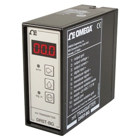
DIN RAIL Signal Conditioner for Load Cells
- Load cell & Strain Gage Amplifier
- MV to Current/Voltage Conversion
- Front-Programmable/LED Display
- Relative Calibration of Input Span
DRST-BG-Load-Cell-Cond
From
€
605,10
Product Overview
- Approvals Note EMC 2014/30/EU EAC: TR-CU 020/2011
- Calibration Temperature, Max 28 °C
- Calibration Temperature, Min 20 °C
- Display Type LED
- Electrical Output 0 to 20 mA
- EMC Standard NAMUR NE 21
- Enclosure Ratings IP50
- Height 80.5 mm
- Length 84.5 mm
- Linearity Error < 0.1% of span
- Load Resistance 230 mA Max;Current Output : 600 Ω
- Mounting DIN Rail Mount
- Noise Calibration >60 dB
- Offset Max Offset: 70 %
- Operating Temperature, Max 60 °C
- Operating Temperature, Min -20 °C
- Output Value Process
- Power Consumption 7.2 W
- Power Dissipation 2.2 W
- Relative Humidity <95% RH
- Series ID DRST-BG-Load-Cell-Cond
- Signal Dynamics Input 17 bit
- Signal Dynamics Output 16 bit
- Stability Load Stability: 0.01% of span/100 Ω
- Supply Power Type DC
- Update Rate 20 ms
- Weight 130 g
- Width 35.5 mm
Brand New DRST-BG MV Signal Transmitter converts bipolar mV signals from transducers supplied directly by the device to standard current/voltage signals. DRST-BG is suitable for load cell application as well as other applications such as tank filling and draining, weighing with a taring function, measurement of cable tensile force, level control, signal conversion/amplification.
Advanced Features
A multifunction user interface consisting of three push buttons and a 3-digit LED display for programming.
Technical Characteristics
• Front error LED.
• The analog input can be programmed for voltage in the range -40 to 100 m Vdc.
• The digital signal can be selected as either NPN or PNP. Taring can either be by way of the digital input or from the front interface.
• The analog output can be programmed to current in the range 0 to 20 mA or voltage in the range • Short circuit protected transducer supply which can be programmed to 5 to 13 Vdc from the front.
• Sense input (with transducer supply used) for compensation for cable resistance to the transducer.
• Mounting for a standard 11-pole socket which can be adapted for DIN rail or plate.
PDFs & Manuals