
Thermocouples are widely used temperature sensors across industrial, laboratory, and commercial applications due to their durability, wide temperature range, and fast response time. However, even a high-quality thermocouple can deliver inaccurate readings if it is installed incorrectly.
Proper installation affects not only measurement accuracy, but also sensor response time, signal stability, and long-term reliability. Factors such as probe placement, immersion depth, wiring polarity, and signal conditioning all play a role in how well a thermocouple performs in real-world applications.
Innovative Solutions from DwyerOmega
Understanding How Thermocouples Measure Temperature
Before installation, it helps to understand how a thermocouple works.
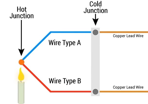
A thermocouple measures temperature based on the Seebeck effect, which occurs when two dissimilar metals are joined at a measurement junction. When the junction experiences a temperature change, a small voltage is generated. That voltage is proportional to the temperature difference between the measurement junction and the reference junction at the instrument.
Because of this principle, a thermocouple always measures its own temperature, not the surrounding air or process by default. Proper installation ensures the thermocouple junction reaches thermal equilibrium with the surface or media being measured.
General Thermocouple Installation Guidelines
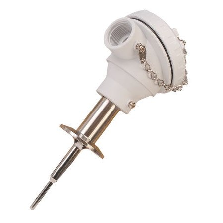
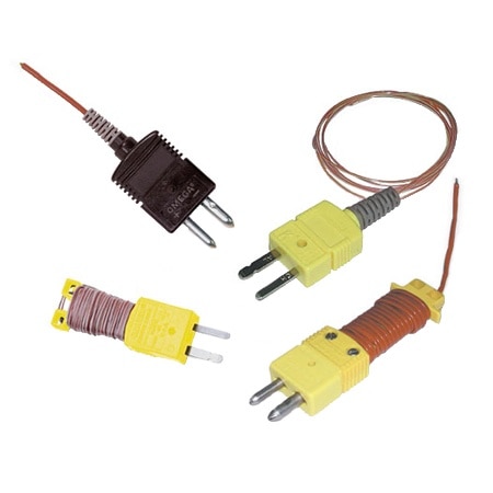
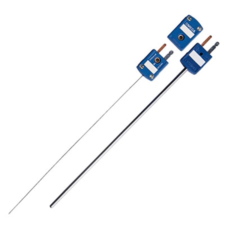
Thermocouples are available in many configurations, including direct immersion probes, thermowell assemblies, surface sensors, handheld probes, and specialty designs. While each style has unique mounting requirements, the following principles apply to nearly all installations:
- The goal is to bring the thermocouple measurement junction to the same temperature as the process or object being measured
- Heat always flows from hot to cold. Metal sheaths, housings, and thermocouple wire conduct heat, which can influence readings if the sensor is not installed correctly
- In immersion applications, the probe must be inserted deeply enough to minimize heat transfer along the stem. This phenomenon is known as stem conduction and depends on process temperature, flow conditions, and ambient temperature
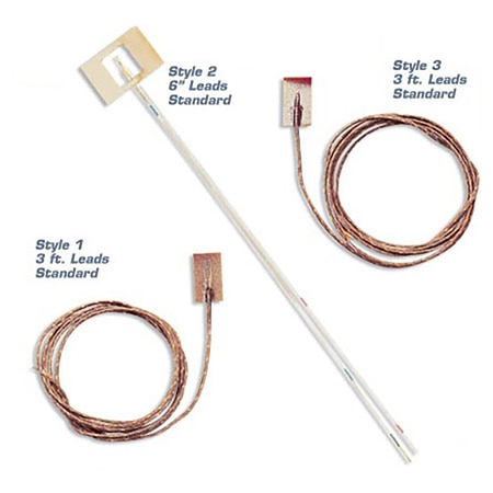
- Surface thermocouples typically use mounting holes, clamps, springs, or adhesive pads to maintain good thermal contact with the surface
- Some thermocouples include threaded process connections. Others require compression fittings, feedthroughs, brackets, or mounting adapters to secure the sensor properly
Wiring Thermocouples Correctly
Thermocouples use two dissimilar metal conductors, which means polarity matters.
- Thermocouples have a positive and negative wire
- For ANSI/ASTM color-coded thermocouples, the negative wire is typically red
- For IEC color-coded thermocouples, the negative wire is typically white
When using extension wire (thermocouple grade or extension grade), only matching thermocouple wire of the same type should be used. For example, a Type J thermocouple must use Type J extension wire. Mixing metals introduces additional junctions and measurement errors.
Thermocouple connectors are polarity-marked and use different pin sizes to prevent mismatching, which helps reduce wiring errors during installation and maintenance.
Connecting Thermocouples to Instruments

When connecting thermocouples to controllers, temperature meters, data loggers, or transmitters, polarity must be maintained all the way to the instrument terminals.
Two of the most common installation mistakes are:
- Crossing the positive and negative leads
- Using copper wire or non-thermocouple extension wire
Using One Thermocouple for Multiple Measurements
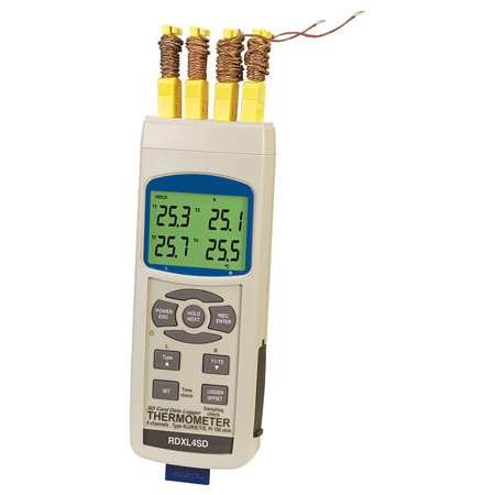
If temperature readings are required at more than one device, a single thermocouple should not be split across multiple instruments.
Instead, dual or multi-element thermocouples should be used. These sensors contain separate, electrically isolated measuring circuits within the same probe. Each output is independent, ensuring that one measurement does not affect the accuracy or stability of the other.
This approach is commonly used in redundant monitoring, safety systems, and control plus indication setups.
Managing Thermocouple Signal Transmission
Thermocouple signals are very low-level millivolt signals, making them susceptible to electrical noise.
Sources of interference include:
- Motors
- Variable frequency drives
- High-voltage power lines
- Radio frequency emitters
For many applications, a more robust solution is to use a temperature transmitter or signal conditioner mounted close to the sensor. These devices convert the thermocouple signal into a 4–20 mA or digital output and provide the cold junction reference at the same time.
The maximum practical thermocouple cable length depends largely on the input capability and noise immunity of the measuring instrument.
Diagnosing Temperature Reading Errors
When troubleshooting inaccurate readings or deciding whether a thermocouple replacement is needed, start with the following checks:
- Verify correct polarity throughout the entire circuit. Remember that red is negative for ANSI/ASTM thermocouples
- Confirm that any extension wire matches the thermocouple type
- Ensure the measuring instrument provides cold junction compensation. This is required when reading thermocouple signals
- Check for electrical noise, especially in grounded junction installations
- Inspect mechanical mounting to ensure proper immersion depth or surface contact

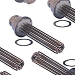
What Is An Immersion Heater? Types Of Immersion Heating Elements What is an Immersion Heater?
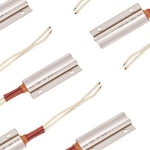
what is an industrial electric heater? What is an industrial heater?