한국 1588-8983 | 새로운 웹사이트에 오신 것을 환영합니다. 문제나 버그를 발견하셨나요? 여기에 보고해주세요


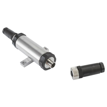
IN-UVI-Bridge-Amplifier
필드 선택 가능 I/O 내장 휘트스톤 브리지 인라인 증폭기
옵션 제공:
- 광범위한 현장 선택 가능 입력 및 출력
- 변환기 연결용 완제품 케이블 어셈블리 출시!
- 입력/출력 절연
- 낮은 열 드리프트


제품 개요
- 승인 CE
- 브리지 저항 350 ~ 5000 Ω
- 보정 사양 참고 현장 설치형 션트 보정 저항기, 브리지 보정을 위한 원격 활성화 포함
- 정전용량 0.022 μF
- EMC <0.15% FS (EN61326-1 산업용 기준)
- 외함 등급 IP65
- 높이 34.8 mm
- 입력 잡음 10 mV 피크 투 피크 @ 3 mV/V 전압 모드 (10 Vdc) 20 uA 피크 투 피크 전류 모드
- 입력 범위 90 mA, 0.5 mV/V ~ 4 mV/V까지 0.5 단계
- 입력 범위 사양 참고 현재: 최대 90 mA (200 mA 공급 가능해야 함), 센서 입력: 0.5 mV/V에서 4 mV/V까지 0.5 단위 증가
- 입력 유형 전류, 신호
- 고립 100 MΩ @ 500 Vdc
- 길이 134.8 mm
- 선형성 0.0001
- 하중 저항 20mA에서 700Ω
- 장기 안정성 FS의 0.1%/년
- 작동 온도, 최대 60 °C
- 최소 작동 온도 -20 °C
- 출력 세부 정보 현재: 4~20mA, 12mA 제로 ±8mA 출력 현장 프로그래밍 가능, 전압: ±5볼트, 최대 2mA에서 ±10볼트
- 출력 저항 60 Ω
- 보호 단락 보호: 예 +출력에서 -출력으로
- 응답 시간 200 µs
- 응답 시간 사양 참고 200 µs (0~63%)
- 감도 브리지 : 5 Vdc EXC에서 1~8 mV/V, 10 Vdc EXC에서 0.5~4 mV/V
- 센서 여기 5 또는 10 Vdc 현장 프로그래밍 가능; 30 mA @ 10 Vdc
- 시리즈 ID IN-UVI-Bridge-Amplifier
- 스팬 조정 ± 20% 미세± 40% 굵은 비율
- 전원 공급 22~32 Vdc
- 공급 전력 참고 출력과 절연된 22~32 Vdc
- 전원 유형 DC
- 열적 스팬 효과 0.0025%/°F
- 열 영점 효과 0.001%/°F
- 트림 팟 접근 커넥터 엔드캡 뒤쪽
- 폭 31.2 mm
- 제로 설정 조절 범위 ± 30%
Supported Applications
The Omega IN-UVI series is a Wheatstone bridge in-line signal conditioner designed for use with miniature transducers, including load cells and pressure transducers. It connects between the sensor and a readout instrument or data acquisition (DAQ) system to convert millivolt signals into standardized voltage or current outputs. The rugged stainless steel enclosure supports deployment where space is limited or environments are hostile.
Operating Conditions & Performance
The IN-UVI operates within an ambient temperature range of -20 to 60°C (0 to 140°F) and provides IP65 environmental protection. It accepts a supply voltage of 22 to 32 Vdc, isolated from the output by 500 Vdc with 100 MΩ resistance. The device features programmable bridge excitation at either 5 or 10 Vdc (field selectable) and supports sensor input ranges from 0.5 mV/V to 4 mV/V in 0.5 steps.
Performance specifications include a linearity of ±0.01% of FS, long-term zero drift of 0.1%/year of FS, and temperature effects of ±0.001%/°F for zero (auto-zero front end) and ±0.0025%/°F for span. The response time is documented as 200 μS (0 to 63%) for a 350 Ω bridge and 1.2 mS for a 5,000 Ω bridge.
Configuration Options
The series offers configurable output signals including voltage options of ±5 Vdc or ±10 Vdc (at 2 mA max) and current outputs of 4-20 mA or 12 mA zero ±8 mA. The maximum load resistance is rated at 700 Ω at 20 mA for current mode, with an output resistance of 60 Ω.
Key configurable features include:
- Excitation Voltage: Field programmable selection between 5 Vdc or 10 Vdc (max excitation current 30 mA @ 10 Vdc).
- Sensor Input Range: Supports bridge sensitivities of 1 to 8 mV/V at 5 Vdc EXC, and 0.5 to 4 mV/V for 10 Vdc EXC.
- Bridge Resistance Compatibility: Accepts transducer resistances from 350 to 5,000 Ω.
- Calibration Features: Includes a buffered solid-state shunt calibration feature that can be remotely activated for field checking and adjustment. Zero adjustment range is ±30% of FS; span adjustment offers ±20% fine and ±40% coarse ranges, accessible behind connector endcaps.
- Electrical Connections: Available with M12 connectors (5-pin or 8-pin) or flying leads. Accessories include the M12.5-S-F-FM for sensor connection and M12.8-S-F-FM for input/output connections, both featuring cable glands.
Key Product Differences
The IN-UVI series is identified by the model number guide CA-4PC24-2A-xxx-INUVI structure when configured with specific Omega cable assemblies. Standard cable part numbers are available for various transducer types, including load cells (e.g., LC111, LCHD) and pressure sensors (e.g., PX35, PX6000). The physical dimensions of the unit are 134.8 mm L x 34.8 mm H x 31.2 mm D (5.3 x 1.37 x 1.23 in), with a diameter of 31.2 mm (1.23 in). The series carries CE certification and includes a one-year warranty.