日本 +81 3 6822 0370 | 新しいウェブサイトへようこそ。問題やバグを見つけましたか?こちらからご報告ください


Miniature-Adjustable-Current-Switches
小型調整可能電流スイッチ
- 過負荷状態
- 低負荷状態
- 通常負荷状態
- ベルト切れ
- ベルト滑り
- ローターのロック
- 電気故障
- 負荷状態
- ストロボ/可聴アラームなどのローカルアラーム
- ポンプ
- ファン
- コンプレッサー
- 照明状態および使用情報
- オーブン
- プロセス制御
- 産業機器
- 機器メンテナンス
- OEM
Miniature-Adjustable-Current-Switches
販売元
166,307
원


製品の概要
- 応用例 空気と空調, 建設と維持管理, コントロールパネル, 環境と気象, 環境モニタリング, 流量測定, 暖房機器, 産業および製造業, OEM, プロセス自動化と制御, 研究開発/エンジニアリング試験
- 電気接続 ネジ端子
- 筐体材質 ABS、ポリカーボネート
- エンクロージャーの定格 UL94 V-0
- ヒステリシス 典型的な10%トリップポイント
- 絶縁 2200 Vac
- LEDインジケータ 赤色LED(トリップポイント以上の電流)
- 材料 ABS
- 測定タイプ 交流電流
- 動作湿度 0~95% RH、結露なし
- シリーズID Miniature-Adjustable-Current-Switches
- 最大保管温度 95 °F
- 保管温度(最低) 41 °F
- 電源タイプ 誘導
- 供給電圧 監視導体から誘導される(絶縁導体のみ)
- スイッチ定格 1 A @ 36 Vac/Vdc
- トルクの締め付け 4.43~5.31 in-lbs.(0.5~0.6 Nm)
- 線径 22から16 AWGまで
Supported Applications
The ACI Miniature Adjustable Current Switch series (Models A/MCS-A and A/MSCS-A) are current monitoring devices designed for AC applications. These switches monitor normal operating conditions, equipment failure, or preventative maintenance scheduling. Documented use cases include detecting overload conditions, broken belts, locked rotors, electrical failures, load status, local alarms, fans, compressors, lighting status, ovens, process control, industrial equipment, and OEM applications. The series is suitable for determining equipment run time, retrofit installations, and service vehicle deployments.
These devices are intended for use on insulated conductors only and do not require external power; sensor excitation is induced from the monitored conductor. They can be used in conjunction with building management systems or PLCs to log contact closures.
Operating Conditions & Performance
The series monitors AC Current up to a maximum of 600 VAC at an operating frequency range of 50/60 Hz. The isolation voltage is rated at 2200 VAC. Ambient temperature limits are -22 to 140°F (-30 to 60°C), with an operating humidity range of 0 to 95%, non-condensing.
Performance characteristics vary by core style:
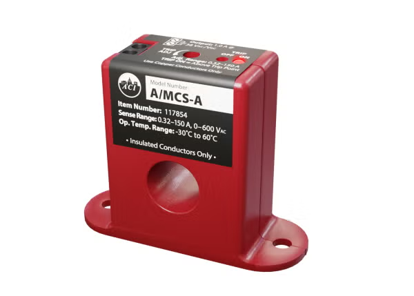
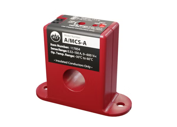
- A/MCS-A (Solid-Core): Response time is < 90 mS, typical. The adjustable trip point and measurement range are 0.32 to 150A.
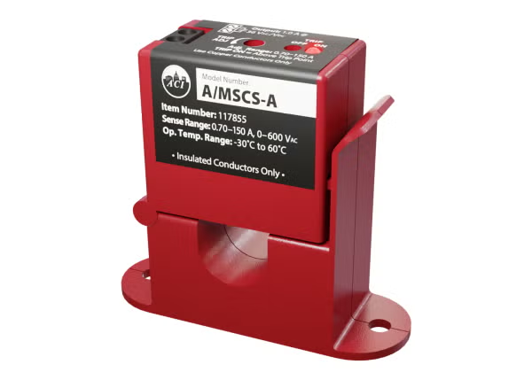
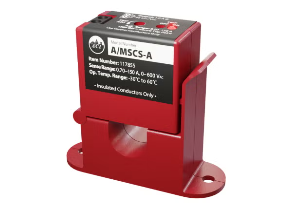
- A/MSCS-A (Split-Core): Response time is < 45 mS, typical. The adjustable trip point and measurement range are 0.70 to 150A.
Hysteresis is specified as 10% Trip Point, typical. Contact resistance is less than 0.5 Ohms (tripped) and greater than 1 Meg Ohm (open). The contact rating is 1A Continuous @ 36 VAC/VDC.
Configuration Options
The series offers two primary configurations distinguished by core style, enabling installation flexibility:
- Solid-Core (Model A/MCS-A): Requires conductor insertion through the aperture. Dimensions are 2.510" (63.82 mm) x 0.940" (23.94 mm) x 2.000" (50.80 mm). Weight is 0.15 lbs. (0.068 kg).
- Split-Core (Model A/MSCS-A): Allows installation without disconnecting wires, suitable for retrofit applications. Dimensions are 2.650" (67.19 mm) x 0.940" (23.94 mm) x 2.380" (60.49 mm). Weight is 0.20 lbs. (0.091 kg).
Both variants feature a 0.53" (13.46 mm) aperture size and are constructed from PC/ABS (Polycarbonate/ABS Blend) with a UL94-VO flammability rating. Electrical connections utilize a 2 Position Screw Terminal Block that is not polarity sensitive, accepting 16 to 22 AWG copper wires only. The terminal block torque rating is 4.43 to 5.31 in-lbs. (0.5 to 0.6 Nm).
Status indication is provided via dual LEDs: a Red LED indicates current above the trip point, and a Blue LED indicates current below the trip point.
Key Product Differences
The primary distinction between models lies in the core design and resulting measurement range:
- A/MCS-A (Solid-Core): Supports an ampereage range of 0.32 to 150A.
- A/MSCS-A (Split-Core): Supports an ampereage range of 0.70 to 150A, offering the ability to clamp around existing conductors without power interruption.
Both models share identical contact ratings (1A @ 36 VAC/VDC), hysteresis specifications, and environmental limits. Agency approvals for the series include UL/CUL US Listed (UL 916) Energy Management Equipment (File # E334792), CE, RoHS2, and WEEE.
Installation requires a minimum mounting distance of 1" (2.6 cm) between the current switch and other magnetic devices such as relays, contactors, or transformers. The series is not intended for Life/Safety applications or use in hazardous/classified locations.