日本 +81 3 6822 0370 | 新しいウェブサイトへようこそ。問題やバグを見つけましたか?こちらからご報告ください



4-20mA-Output-Current-Sensor
アナログ電流センサー、4-20mA
아날로그 전류 센서, 4-20mA- 負荷トレンド
- 基本的な電力監視
- 電子バラスト
- コンピュータ/データセンター
- 産業用
- 可変速負荷
- ポンプ
- コンプレッサー
- ファン
- 予防保全
- LEED
- プロジェクト正当化(ROI)プロセス制御
- 固体環境(SCR)
4-20mA-Output-Current-Sensor
From
319,582
원


Product Overview
- 精度 ± 1 %
- 精度の詳細 すべてのモデル:選択範囲の±1%、ただしA/SCTA2-50-RMSは15 Hz~20 Hzで±2%、20 Hz~100 Hzで±1%
- 応用例 空気と空調, 建設と維持管理, 電子機器, 環境モニタリング, 流量測定, 産業および製造業, 研究開発/エンジニアリング試験
- ケーブルタイプ 絶縁・シールド
- 校正に関する注記 すべての現在の出力センサーは、環境室温21.5 °C(71 °F)で校正されています。
- 電気接続 ネジ端子
- 電気出力 0~20 mA
- 筐体材質 ABS、ポリカーボネート
- エンクロージャーの定格 UL94 V-0
- 絶縁 2200 Vac
- 材料 ABS
- 測定タイプ 現在
- 動作温度(最高) 104 °F
- 動作温度(最低) 5 °F
- 相対湿度 0~95%、非結露
- シリーズID 4-20mA-Output-Current-Sensor
- 最大保管温度 95 °F
- 保管温度(最低) 41 °F
- 供給電流 25 mA、ミニット
- 電源注記 +8.5 Vdc から 30 Vdc(逆極性保護付き);250 オーム負荷(1 Vdc から 5 Vdc):+13.5 Vdc から 30 Vdc;500 オーム負荷(2 Vdc から 10 Vdc):+18.5 Vdc から 30 Vdc
- 供給電圧 8.5から30Vdc
- トルクの締め付け 0.5 Nm~0.6 Nm(4.43 in-lb~5.31 in-lb)
- 線径 24から18 AWGまで
Supported Applications
The ACI Analog Current Sensor, 4-20 mA series is designed for monitoring resistive loads and single-speed linear applications. Documented use cases include incandescent light bulbs, heating elements, and equipment requiring pure sinusoidal waveform monitoring. The "True RMS" variants extend application suitability to environments with distorted waveforms or noise, including Variable Frequency Drives (VFDs), switching power supplies, computers, data centers, electronic ballasts, SCRs, and variable speed loads.
These sensors are not intended for life or safety applications nor for use in hazardous or classified locations. The series supports both new installations via solid-core versions and retrofit scenarios using split-core models that allow installation without disconnecting wires.
Operating Conditions & Performance
The series monitors AC current with a maximum voltage rating of 600 Vac and an isolation voltage of 2200 Vac. Operating temperature ranges from -15 °C to 40 °C (5 °F to 104 °F) in ambient conditions, while storage is specified between 5 °C to 35 °C (41 °F to 95 °F). Humidity tolerance covers 0 % to 95 %, non-condensing during operation and 40 % to 85 % RH for storage.
Accuracy specifications vary by model type. All models generally provide +/- 1 % of the selected range, with the exception of A/SCTA2-50-RMS which offers +/- 2 % from 15 Hz to 20 Hz and +/- 1 % from 20 Hz to 100 Hz. Response times differ by measurement style: A/SCTA2-XXX models exhibit a rise and fall time of less than 600 mS, while A/CTA2-xxx-RMS and A/SCTA2-50-RMS show a 600 mS rise time and 2800 mS fall time.
Operating frequency ranges are model-specific: the A/SCTA2 Series covers 40 KHz to 1 KHz; A/CTA2-50-RMS & A/SCTA2-50 RMS cover 15 Hz to 100 Hz. For A/CTA2-250-RMS, the range is 15 Hz to 100 Hz for the 0 A to 100 A setting and 30 Hz to 100 Hz for the 0-200/250 A ranges.
Configuration Options
The series is available in solid-core and split-core configurations, both featuring a patented (Pat. No. US 7,416,421) 35 mm DIN Rail mounting foot. The enclosure material is PC/ABS (Polycarbonate/ABS Blend) with a UL94-V0 flammability rating.
Key configurable parameters include:
- Core Style: Solid-core versions are suited for new installations or OEM applications; split-core versions facilitate retrofit and field service without wire disconnection.
- Measurement Type: "Average" style sensors monitor pure sinusoidal waveforms, while "True RMS" sensors handle distorted waveforms found in VFDs and electronic loads.
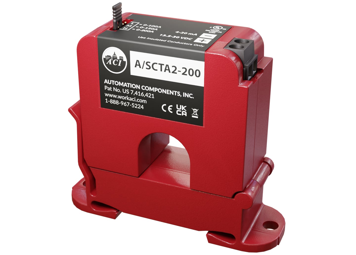
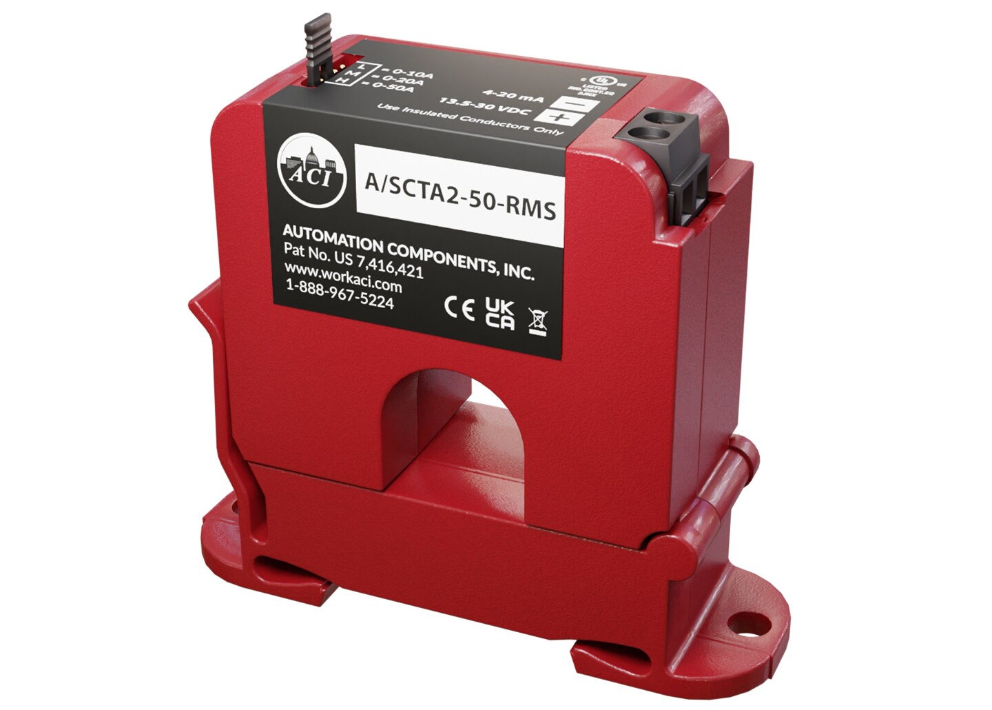
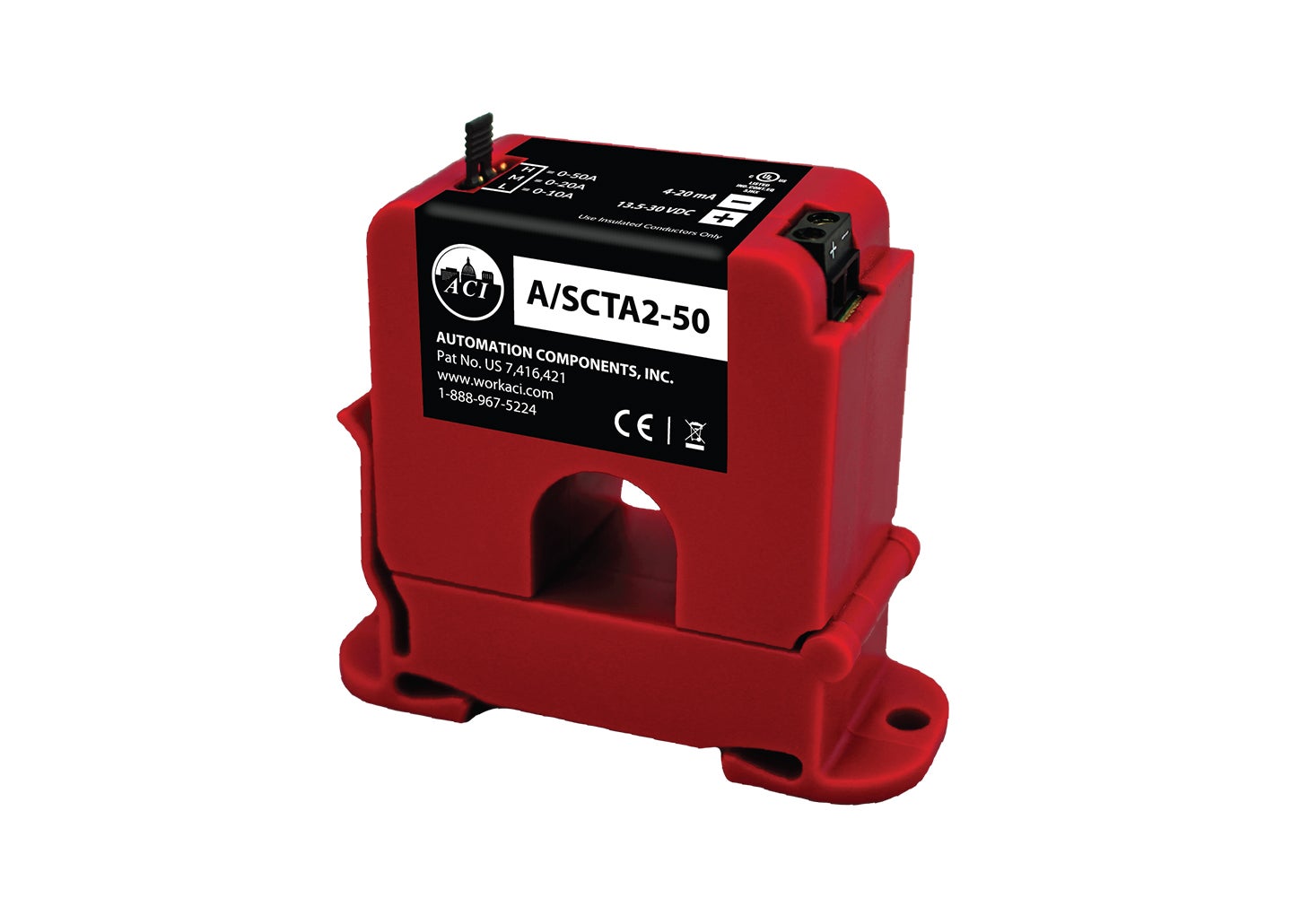
- Selectable Ranges: Models offer ranges such as 0 A to 10/20/50 A; 0 A to 100/150/200 A; and 0 A to 100*/200/250 A.
- Output Signal: All models provide a 4 mA to 20 mA (2-Wire, Loop Powered) output limited to 25 mA maximum. Voltage conversion options are available via external resistors for 1 Vdc to 5 Vdc or 2 Vdc to 10 Vdc outputs.
- Power Supply: Requires +8.5 Vdc to 30 Vdc (Reverse Polarity Protected). Specific load resistance requirements apply: +13.5 Vdc to 30 Vdc for a 250 Ohm Load and +18.5 Vdc to 30 Vdc for a 500 Ohm Load.
Wiring utilizes a 2-position screw terminal block (polarity sensitive) compatible with 0.823 mm² to 0.205 mm² (18 AWG to 24 AWG) copper wires only, shielded cable recommended. The aperture size is fixed at 19.05 mm (0.75 in).
Key Product Differences
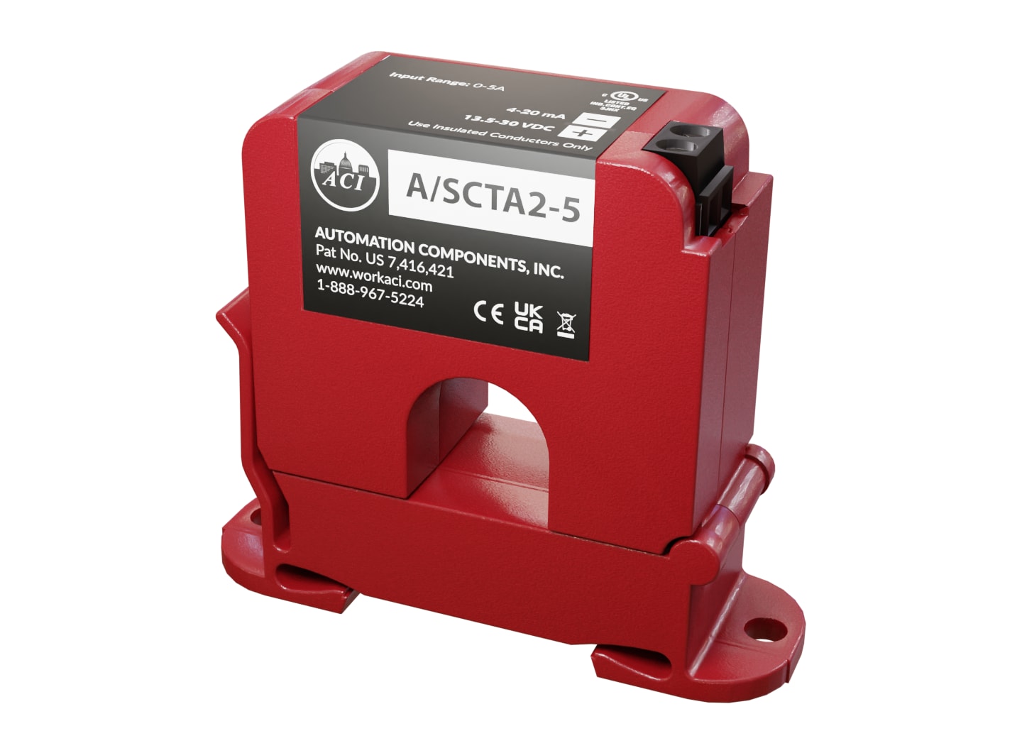
The series distinguishes between "Average" and "True RMS" measurement technologies to address waveform distortion. Solid-core models are identified by the A/CTA2 prefix, while split-core models use the A/SCTA2 prefix.
- Average Models: Designed for pure sinusoidal waveforms (e.g., resistive loads). Examples include A/CTA2-50 and A/SCTA2-50.
- True RMS Models: Provide best overall accuracy in applications with distortion, such as VFDs or switching power supplies. These models carry the "-RMS" suffix (e.g., A/CTA2-50-RMS, A/SCTA2-50-RMS).
- Ranging Differences: The A/CTA2-250-RMS supports selectable ranges of 0 A to 100*/200/250 A. Note that only the 0 Amp to 100 Amp range in this specific model meets accuracy specifications from 15 Hz to 100 Hz.
Physical dimensions differ slightly by core style: Solid-core versions measure 70.11 mm (2.760 in) x 84.92 mm (3.343 in) x 26.67 mm (1.050 in), while split-core versions are 70.51 mm (2.780 in) x 82.25 mm (3.238 in) x 28.45 mm (1.120 in). Weights vary by model family, with A/SCTA2-xxx at 0.124 kg (0.274 lb) and RMS variants typically weighing 0.087 kg (0.190 lb).
PDFs & Manuals