한국 1588-8983 | 새로운 웹사이트에 오신 것을 환영합니다. 문제나 버그를 발견하셨나요? 여기에 보고해주세요



Series-SPPM2
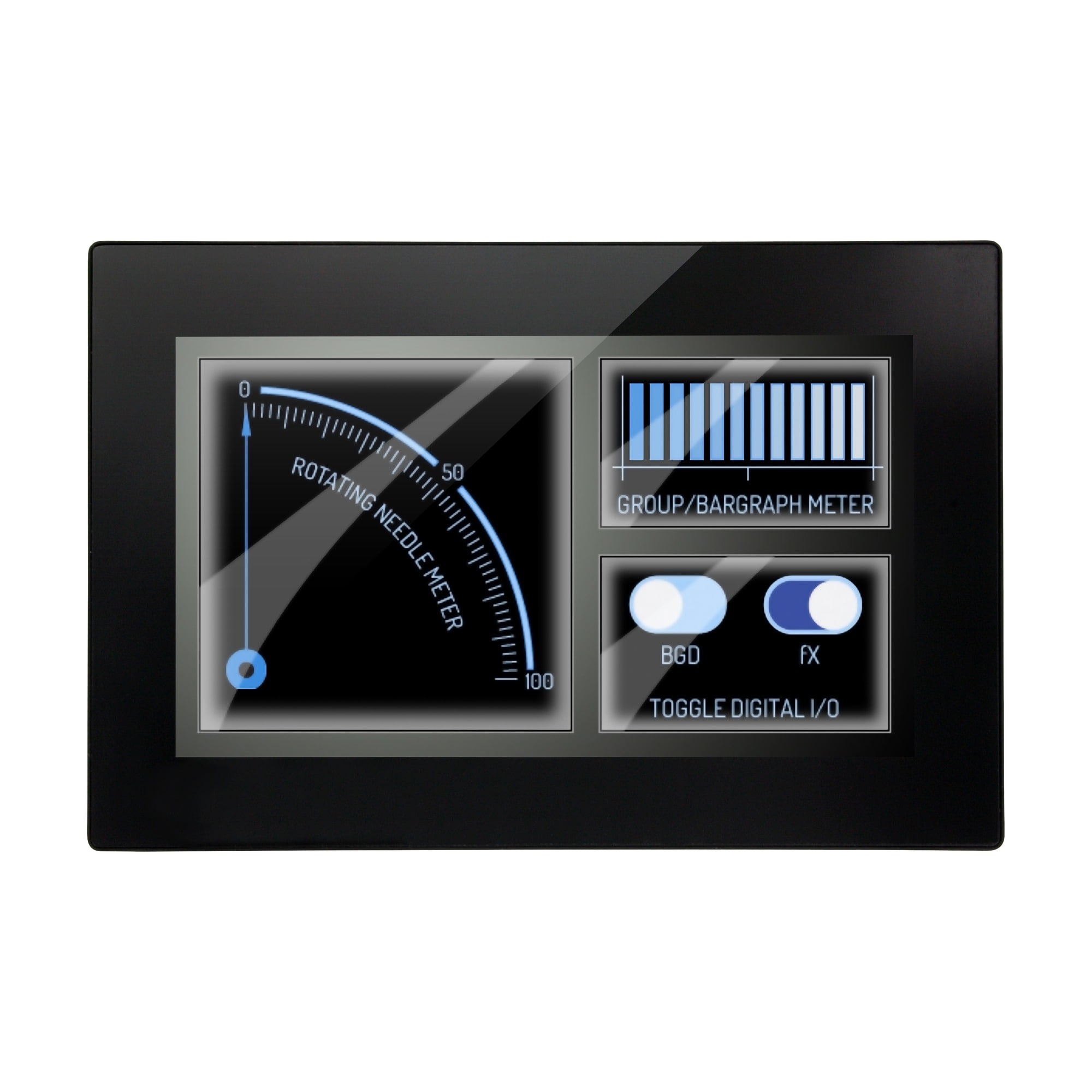
4.3" 터치 스크린 패널 미터 제어 및 모니터링용 - 개발 키트 포함
- 대형 4.3" 터치 스크린 디스플레이는 USB 또는 5~30 Vdc 전원으로 구동 가능
- 무료 디자인 소프트웨어를 통해 사용자가 화면에 요소를 드래그 앤 드롭하여 특정 인터페이스를 빠르게 개발할 수 있음
- 최대 4개의 아날로그 입력, 8개의 디지털 I/O, 4개의 PWM 출력, 2개의 오픈 컬렉터 알람 출력 지원


제품 개요
- 정확도 ± 0.05% ± 0.1 mV
- 응용 분야 펌프 제어, 냉장, 냉동 장비
- 전류 측정 범위 4 ~ 20 mA
- 디스플레이 노트 4.3" (10.9 cm) TFT LCD, 262k 색상
- 디스플레이 해상도 480 x 272 픽셀
- 디스플레이 유형 컬러 LCD
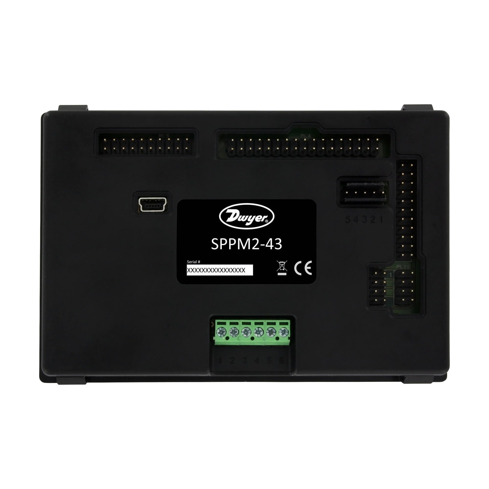
- 전기 연결 나사 단자; 여러 개의 DIL IDC 소켓; USB 미니 B
- 입력 유형 전압, 전류, 디지털 입출력
- 장착 패널 장착
- 작동 온도, 최대 104 °F
- 최소 작동 온도 32 °F
- 출력 세부 정보 펄스 스위치 변조 4개, 오픈 컬렉터 알람 2개
- 전력 소비 400 mA
- 해상도 최대 0.04 mV
- 해상도 사양 참고 0.04 mV (최대) 또는 소수점 이하 4자리
- 샘플링 속도 10 Hz (초당 10회 업데이트)
- 시리즈 ID Series-SPPM2
- 전원 유형 DC/USB
- 공급 전압 5 ~ 30 Vdc
- 시스템 요구사항 Windows® 7, Windows® 8 및 Windows® 10과 호환됨
- 워밍업 시간 15 s
Supported Applications
The Dwyer Series SPPM2 is a configurable Graphical User Interface (GUI) panel meter featuring a full-color 4.3" touch screen display designed for control and monitoring applications. Users personalize the interface using free Windows® based Interface Panel Design Studio software to create custom displays with buttons, switches, analog scales, and digital indicators tailored to specific operational needs.
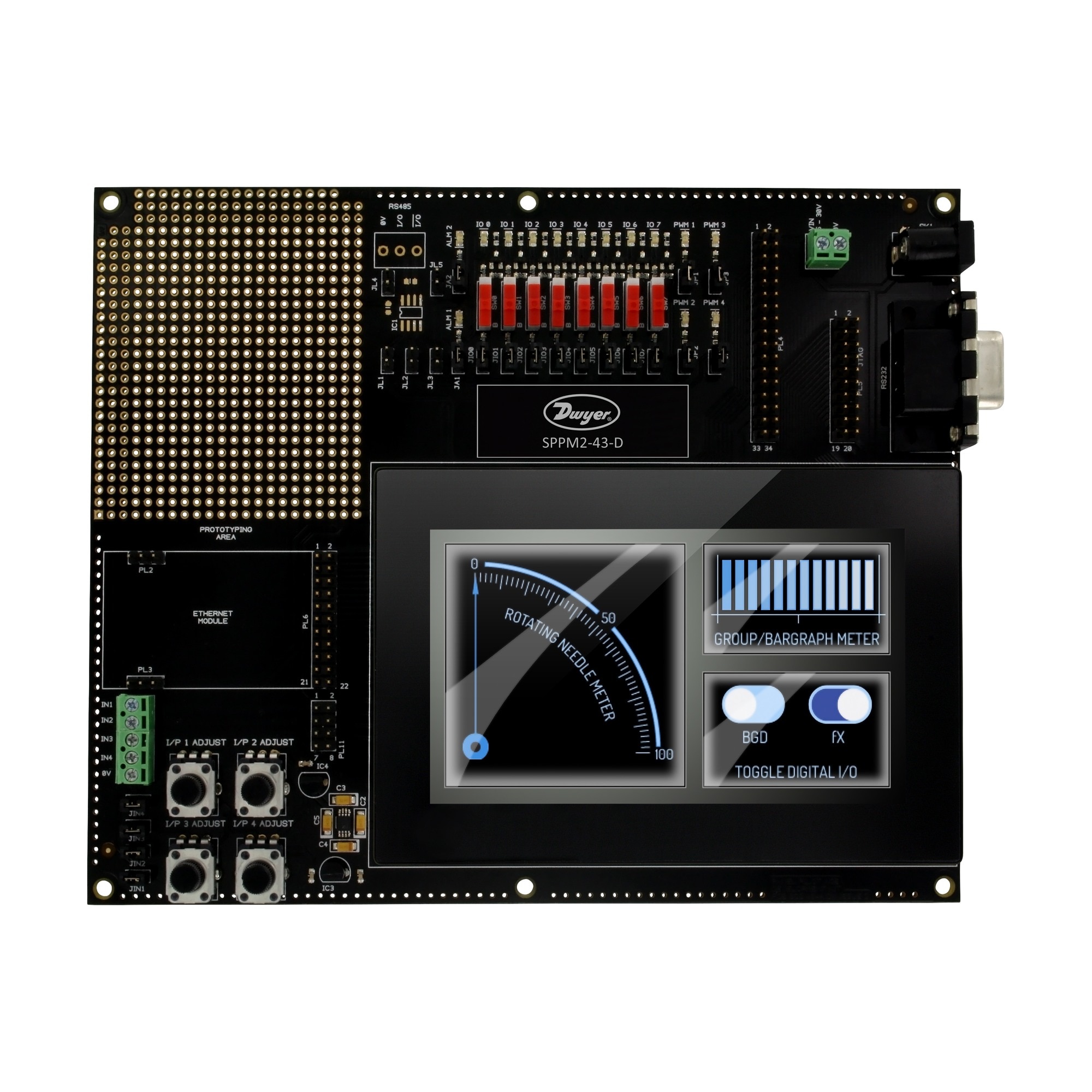
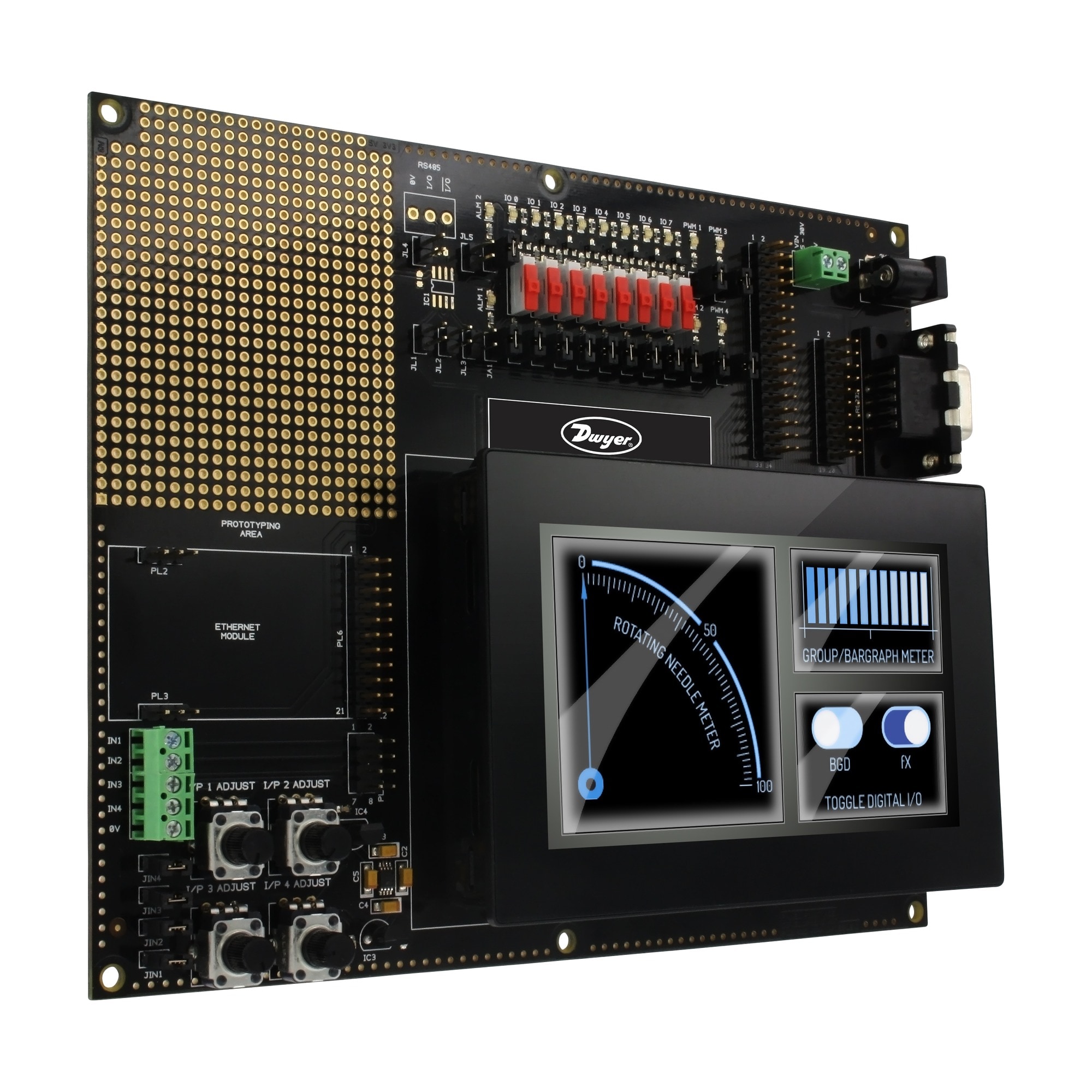
A development kit is available as an option (included in model SPPM2-43-D), providing a board equipped with physical buttons, dials, LEDs, and screw terminals. This accessory allows engineers to test the functionality of all inputs and outputs during system design and prototyping phases.
Operating Conditions & Performance
The Series SPPM2 operates within an ambient temperature range of 32 to 104°F (0 to 40°C). The unit requires a warm-up period of 15 sec before reaching full performance specifications. Power is supplied via the USB port or an external source ranging from 5 to 30 VDC, with current consumption specified at 400 mA at 5 VDC.
Performance metrics for analog measurements include:
- Accuracy: ±0.05% ±0.1 mV (typ)
- Resolution: 0.04 mV (max) or 4 decimal places
- Sampling Rate: 10 samples/sec
- Analog Input Ranges: ±2.5 V, ±5 V, ±10 V, ±20 V, and ±40 V; plus 4 to 20 mA current loop capability.
The display is a 4.3" (109 mm) TFT LCD with 262k colors and a resolution of 480 x 272 pixels. The unit utilizes a programmable gain amplifier (PGA) paired with a 16-bit analog-to-digital converter (ADC), where the PGA is automatically set based on the channel range defined in the design software.
Configuration Options
The Series SPPM2 supports extensive I/O configuration through multi-pin DIL connectors, screw terminals, and serial interfaces. Key configurable capabilities include:
- Analog Inputs: 4 channels supporting ±40 V or 4 to 20 mA current loop measurements via a 6-line screw terminal block.
- Digital I/O: 8 digital input/output channels available for discrete control and status monitoring.
- PWM Outputs: 4 Pulse Width Modulation outputs with source/sink currents up to -9.5 mA / 7.7 mA respectively, operating at logic levels between 0 V and 3.3 V.
- Alarm Outputs: 2 open collector alarm channels (ALM1, ALM2).
- Communication & Connectivity: Mini-USB interface for power/data; RS232 serial communication port; JTAG programming interface; and expansion I/O headers.
The unit is designed for panel mount installation with overall dimensions of 4.45/64 [119.30] x 3.49/64 [95.84] x 2.5/32 [54.68] inches (or mm). Electrical connections are made via multi-pin DIL connectors, one mini-USB port, and one RS232 interface.
Key Product Differences
The Series SPPM2 is offered in two primary configurations based on the inclusion of development hardware:
- SPPM2-43: The standard 4.3" graphical user interface panel meter.
- SPPM2-43-D: Includes the SPPM2 unit plus a Development Kit containing a development board with buttons, dials, LEDs, and screw terminals for testing inputs and outputs.
The Series SPPM2 carries CE approval. The device is not field serviceable; attempting repairs may void the warranty. For optimal measurement accuracy regarding analog grounds, it is recommended to connect them directly to the meter pins (PL11) or screw terminals (TBLK1).
PDF 및 매뉴얼


