
In industrial process control and applications like HVAC maintenance, sensors used to measure pressure, temperature, humidity, or gas concentration are often available with multiple output signal options. These different output types exist largely to ensure compatibility with the input options of the wide range of programmable logic controllers (PLCs) and direct digital controllers (DDCs) used in automation and for building control systems.
While many signal formats are available, two of the most common analog output types are analog voltage, typically 0–10 VDC, and analog current, most commonly 4–20 mA. Each offers distinct advantages and disadvantages depending on the application, installation conditions, and maintenance requirements.
0–10 Analog Voltage Outputs
Since a large number of industrial controllers are designed to accept it, the 0-10 VDC analog voltage signal is one of the most widely used output types in both process and HVAC instrumentation.
One frequently cited advantage of a 0–10 VDC output is ease of verification. Installers and service technicians can simply connect a voltmeter in series to measure the output voltage and directly correlate that reading to the sensor’s measurement range, making basic troubleshooting and signal confirmation relatively straightforward.
However, analog voltage signals are more susceptible to electrical interference. Nearby motors, relays, or other electrically noisy devices can introduce interference that affects signal accuracy. Long cable runs, needed when sensors are installed far from the controller, can introduce increased wire resistance which leads to voltage drop.
4–20 mA Analog Current Outputs
Analog current outputs, typically 4–20 mA, are commonly used where signal integrity and reliability are more critical. Unlike voltage signals, the magnitude of the current in a current loop is not affected by voltage drops in the wiring. Because the current leaving the negative side of the loop must return to the positive side of the power supply, long cable runs do not degrade the signal in the same way they can with voltage outputs.
Current signals also offer increased immunity to electrical interference, making them well suited for environments with motors, relays, or other sources or electrical noise.
One drawback of 4–20 mA outputs is that signal verification can be more difficult to achieve. To read the output with a voltmeter, a precision resistor is typically required to convert the current signal into a voltage using Ohm’s Law. This adds an extra step compared to directly measuring a voltage output.
However, a key advantage of the 4–20 mA signal is fault detection. If a wire breaks in the loop, the signal drops to 0 mA, clearly indicating a wiring issue. With basic 0–10 V outputs, a broken wire may not be as obvious. Some voltage-based systems address this limitation by using alternative ranges such as 1–5 V or 2–10 V to help indicate fault conditions.
Innovative Solutions from

Series LTTJ Adjustable Current Transformers
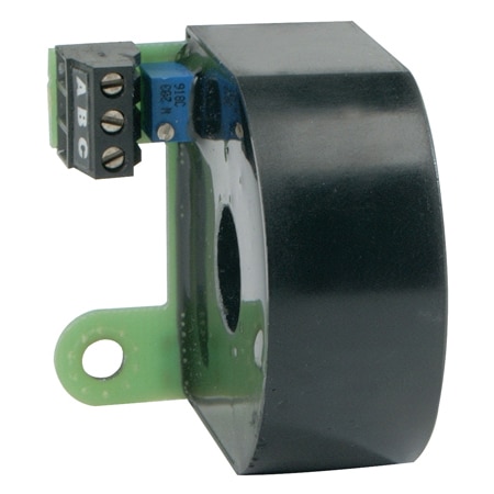
The Series LTTJ Adjustable Current Transformers provide a simple way to monitor load current while delivering a 0–10 VDC analog output compatible with both high- and low-impedance inputs. This makes them easy to integrate with PLCs, DDCs, and other voltage-based control and monitoring systems.
Designed for flexibility, the LTTJ Series offers fully adjustable output scaling, impedance matching, and built-in overvoltage protection to help ensure stable, reliable signal transmission. Select models include an LED indicator for quick visual confirmation that current is flowing, which is especially useful during commissioning and troubleshooting.
Available in multiple current ranges, these transformers can be conveniently mounted directly to most LTP Series solid state relays, simplifying installation and wiring. The LTTJ Series from Love Controls is well suited for applications where accurate current monitoring needs to be converted into a standard 0–10 VDC control signal.
PX409 Series High-Accuracy Pressure Transducers
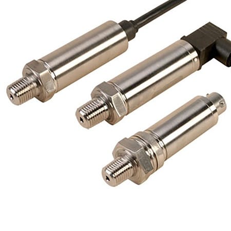
The PX409 Series Pressure Transducers are designed for applications where precision, stability, and signal quality are critical. With a configurable output that supports common analog standards, including 0–10 VDC and 4–20 mA, the PX409 Series integrates easily with PLCs, DAQs, and high-performance control systems across commercial, industrial, and aerospace environments.
Built around a micro-machined silicon sensor with a full Wheatstone bridge, these transducers deliver ±0.08% BSL accuracy, fast response, and excellent long-term stability. All-stainless-steel wetted parts, welded construction, and advanced temperature compensation allow reliable operation in demanding process conditions.
Each PX409 is calibrated using high-accuracy equipment and shipped with a 5-point NIST-traceable calibration certificate, ensuring confidence in both voltage and current signal performance.

Grippers Introduction to Grippers