Resistance Temperature Devices (RTDs) are widely used in industrial and commercial applications due to their accuracy and stability. However, RTD wire configuration can significantly impact measurement precision. Selecting the right configuration ensures optimal performance, minimizes errors, and enhances system reliability.
Innovative Solutions from DwyerOmega
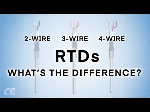
Understanding RTD Wire Configurations
RTDs are typically manufactured in three different wiring configurations: 2-wire, 3-wire, and 4-wire. Each configuration is designed to compensate for lead wire resistance to varying degrees, impacting measurement accuracy. The 2-wire setup is the simplest but most susceptible to errors from lead resistance, making it suitable for shorter wire runs or applications where high precision is not critical. The 3-wire configuration offers better compensation and is commonly used in industrial settings where moderate accuracy is required. The 4-wire configuration provides the highest level of accuracy by fully eliminating lead wire resistance effects, making it ideal for laboratory and high-precision applications.
| RTD Configuration | Description | Pros | Cons | Best For | Construction |
|---|---|---|---|---|---|
| 2-Wire RTD | The most basic RTD configuration, using a single lead wire on each end of the sensing element. Lead wire resistance is included in the measurement, which can introduce errors. |
Simple design Low cost |
Lead wire resistance affects accuracy Not suitable for long cable runs |
Short-distance applications where high precision is not critical, such as basic temperature monitoring |
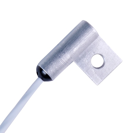
2-Wire RTD Construction
|
| 3-Wire RTD | The most common industrial RTD configuration. Uses two wires on one side of the element to compensate for lead wire resistance. |
Good accuracy for most industrial uses Cost-effective Widely supported by controllers |
Assumes equal lead resistance Small errors possible with long or uneven cable runs |
Industrial temperature monitoring where a balance of accuracy and cost is required |
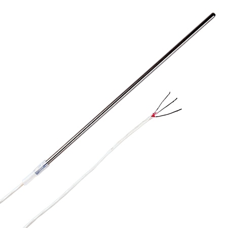
3-Wire RTD Construction
|
| 4-Wire RTD | The most accurate RTD configuration. Uses separate excitation and measurement leads to eliminate lead wire resistance entirely. |
Highest possible accuracy Completely eliminates lead wire resistance |
More complex wiring Higher system cost |
High-precision applications such as laboratory research, calibration systems, and critical industrial processes |
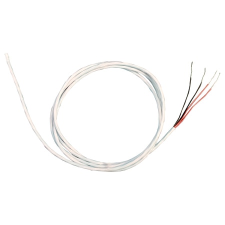
4-Wire RTD Construction
|


What are the Differences Between 2-Wire, 3-Wire, and 4-Wire RTDs?
The primary difference between 2-wire, 3-wire, and 4-wire RTDs lies in how each configuration handles lead wire resistance, which directly affects measurement accuracy. As the number of lead wires increases, the measurement system becomes better able to compensate for resistance introduced by the connecting cables.
2-wire RTDs are the simplest configuration, using one lead wire connected to each end of the sensing element. In this setup, the resistance of the lead wires is added directly to the measured resistance of the RTD element. This makes 2-wire RTDs the least accurate option, especially when longer cable runs are involved. They are typically used in short-distance applications where cost and simplicity are more important than precision.
3-wire RTDs add a third lead wire to help compensate for lead resistance. By using two wires on one side of the RTD element and one on the other, most temperature controllers can mathematically cancel out the resistance of the lead wires, assuming they are equal in length and resistance. This approach significantly improves accuracy compared to a 2-wire configuration and is why 3-wire RTDs have become the most common choice in industrial temperature measurement.
4-wire RTDs provide the highest level of accuracy by completely eliminating the effect of lead wire resistance. This configuration uses one pair of wires to supply excitation current and a separate pair to measure the voltage drop across the RTD element. Because the measurement circuit draws virtually no current, lead wire resistance does not influence the reading. As a result, 4-wire RTDs are preferred in laboratory environments, calibration systems, and critical processes where precision is paramount.
In practice, the choice between 2-wire, 3-wire, and 4-wire RTDs is a balance between required accuracy, system complexity, and cost. For most industrial applications, a 3-wire RTD provides the best combination of performance and practicality, while 2-wire and 4-wire configurations serve more specialized roles.
Choosing the Right RTD Configuration
Selecting the appropriate RTD configuration depends on the application’s accuracy requirements, wiring complexity, and budget. A 2-wire RTD may be sufficient for shorter runs or less critical measurements, while a 3-wire setup balances accuracy and cost for many industrial applications. For the highest precision, a 4-wire RTD is preferred, though it requires more complex wiring and higher installation costs.
Environmental factors such as electrical noise and temperature fluctuations should also be considered, as they can influence measurement accuracy and may necessitate a more robust configuration. Additionally, the type of instrumentation used to process the RTD signal plays a role in determining the most suitable wiring setup, as some systems are designed to work optimally with a specific configuration. Proper installation and maintenance further ensure long-term reliability, preventing errors caused by degraded connections or improper wiring practices.
FAQs
Answer: A 2-wire RTD is typically used in short cable runs where accuracy requirements are modest. Because lead wire resistance is not compensated, this configuration is best suited for cost-sensitive or non-critical applications where small measurement offsets are acceptable.
Answer: A 3-wire RTD offers a balance between accuracy and installation complexity. By compensating for lead wire resistance using a third conductor, it significantly reduces measurement error while remaining compatible with most industrial transmitters, controllers, and PLC input cards.
Answer: A 4-wire RTD provides the highest measurement accuracy by completely eliminating lead wire resistance from the measurement. Two wires supply the excitation current while two separate wires measure voltage across the RTD element. This configuration is commonly used in precision measurement, calibration, and laboratory environments.
Answer: RTD wire color codes vary by standard and manufacturer, but a common 3-wire RTD uses two wires of the same color and one wire of a different color. The matching wires indicate the compensation leads. Always confirm wiring using the sensor datasheet or applicable IEC or ANSI standards.
Answer: A 4-wire RTD can be connected to a 3-wire RTD input by combining two of the leads, but this removes the full lead resistance compensation benefit of the 4-wire configuration. While acceptable in some cases, maximum accuracy requires a true 4-wire input.
Answer: Yes, RTD wire length affects accuracy in 2-wire and, to a lesser extent, 3-wire configurations due to lead resistance. Longer cable runs increase measurement error. A 4-wire RTD largely eliminates wire length effects, making it the preferred choice for long runs or high-accuracy applications.

What Is An Immersion Heater? Types Of Immersion Heating Elements What is an Immersion Heater?
what is an industrial electric heater? What is an industrial heater?