1-800-663-4209 | Welcome to our new website, found an issue or bug? Please report it here
FMA6500-Series
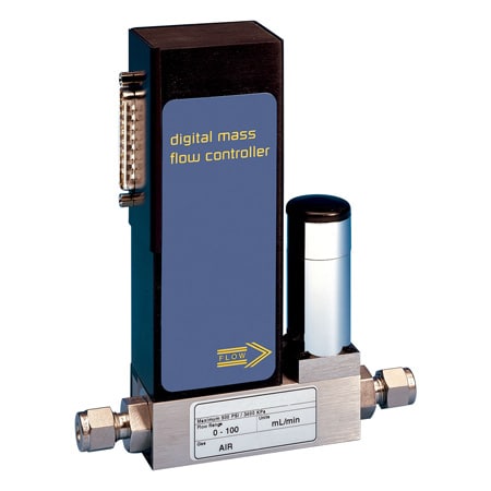
Mass Flow Controller with RS485 Standard and Alarm Functions
- Digital and Analog Modes Operate Simultaneously
- Programmable Flow Configurations
- RS485 Standard, Multi-Drop Capability of Up to 256 units
- Stores Calibration Data for Up to 10 Gases
FMA6500-Series
From
C$
3,529.13
Product Overview
- Accuracy ± 1 %
- Accuracy Detail Accuracy (including linearity): 15 to 25°C (59 to 77°F) and 0.7 to 4 bar (10 to 60 psia): ± 1% of FS, 0 to 50°C (32 to 122°F) and 0.3 to 10 bar (5 to 150 psia): ± 2% of FS, ± 1% of FS at a specific temperature and pressure with special calibration
- Additional Features 1 2 SPDT 1A Relay
- Calibration NIST 10-Point Certificate
- Circuit Protection Reverse polarity, Current Limit, Resettable Fuse
- Control Valve Solenoid Valve
- Data Interface RS485
- Data Interface Note RS485, standard; RS232, optional
- Display Type None
- Electrical Connection Sub-D Male Miniature Connector
- Electrical Output 0 to 5 V
- Enclosure Ratings Inst. Level II/Poll. Degree II (IEC 60664)
- Leak Rate Under Vacuum less than 10^⁻9 cc He/s
- Media Compatibility Clean dry air / inert gas, HVAC / room air, Inert / non-reactive gases, Oxygen
- Operating Pressure, Max 500 psi
- Operating Pressure, Min 0 psi
- Operating Temperature, Max 50 °C
- Operating Temperature, Min 5 °C
- Optimum Pressure 25 psi
- Output Detail Linear 0 to 5 Vdc (2000 Ω min load impedance); 0 to 10 Vdc (4000 Ω min impedance); 4 to 20 mA optional (0 to 500 Ω loop resistance)
- Output Signal Voltage
- Pressure Coefficient 0.01% FS/psi
- Measurement Pressure, Max 50 psi
- Process Connection Size 1/4 in
- Repeatability ± 0.15%
- Response Time 1 sec
- Response Time Note 0.6 to 1.0 s to within ± 2% of setpoint over 20% to 100% FS
- Series ID FMA6500-Series
- Supply Current Up to 450 mA
- Temperature Coefficient 0.05% FS/°C
- Turndown Ratio 50:1
- Volumetric Flow Rate, Min 0.2 SCCM
Microprocessor driven digital flow controllers allow one to program, record, and analyze flow rates of various gases with a computer via an RS485 interface (optional RS232 is available). Controllers can be programmed for various control functions including flow setpoint, totalizer, stop totalizer, read totalizer, totalizer from preset flow, stop at preset total, auto zero, and more.
Principles of Operation
Metered gases are divided into two laminar flow paths, one through the primary flow conduit, and the other through a capillary sensor tube. Both flow conduits are designed to ensure laminar flows and, therefore, the ratio of their flow rates is constant. Two precision temperature sensing windings on the sensor tube are heated, and when flow takes place, gas carries heat from the upstream to the downstream windings. The resultant temperature differential is proportional to the change in resistance of the sensor windings. A Wheatstone bridge design is used to monitor the temperature dependent resistance gradient on the sensor windings which is linearly proportional to the instantaneous rate of flow. The output of the Wheatstone bridge is converted to digital format with a 12 Bit ADC (analog to digital converter). An on-board microprocessor and nonvolatile memory store all calibration factors and directly control a proportional electromagnetic valve. The digital closed loop control system continuously compares the mass flow output with the selected flow rate. Deviations from the setpoint are corrected by compensating valve adjustments, with PID algorithm thus maintaining the desired flow parameters with a high degree of accuracy. Output signals of 0 to 5 Vdc or 4 to 20 mA are generated indicating mass molecular based flow rates of the metered gas.
Interface
The digital interface operates via RS485 (optional RS232) and provides access to applicable internal data including FLOW SETPOINT, ACTUAL FLOW, ZERO ADJUSTMENTS, and LINEARIZATION TABLE ADJUSTMENTS. The analog interface provides 0 to 5 Vdc, 0 to 10 Vdc and 4 to 20 mA inputs and outputs.
Auto Zero
The FMA6500 automatically nulls the sensor zero offset whenever the flow setpoint is below 2% of full scale. To accommodate this feature the control valve must fully close under that condition. Provisions are made to either disable, force or store the current auto zero via digital commands.
Totalizer
The firmware for the FMA6500 provides functions to register total gas quantity. The total mass of gas is calculated by integrating the actual gas flow rate with respect to time. Digital interface commands are provided to: SET the totalizer to ZERO; START /STOP totalizing the flow; READ the totalizer; START the totalizer at a preset flow STOP the flow at a preset total.
Multi-Gas Calibration
The FMA6500 is capable of storing primary calibration data for up to 10 gases. This feature allows the same FMA6500ST to be calibrated for multiple gases while maintaining the rated accuracy on each.
PDFs & Manuals
Accessories
accessories
25 pin D-conn with 1.8 m (6 ft) wire to 15 pin DM, branch 1.8 m (6 ft), wire to computer port stripped
C$191.46 / each
0 In Stock
European power supply with 25 pin female D-conn 230 Vac (±15 Vdc) branch 1.8 m (6 ft) wire to computer port stripped
C$705.90 / each
0 In Stock
UK power supply with 25 pin female D-conn 230 Vac (±15 Vdc) branch 1.8 m (6 ft) wire to computer port stripped
C$545.58 / each
0 In Stock
cables
Replacement cable 25 pin D-conn with 1.8 m (6 ft) wire, branch to power supply
C$150.80 / each
2 In Stock
Power supply with 25 pin female D-conn 110Vac (±15 Vdc) branch 1.8 m (6 ft) wire to analog interface
C$634.09 / each
0 In Stock
Show Ratings & Reviews
We want a device to flow between 0.5 and 1.5 sccm Hydrogen. What sort of resolution can we achieve on the device with 0-10sccm FS? The specs say the accuracy is +/- 1%. Does that mean we can adjust in 0.1 sccm increments? What does turndown ratio mean?
Thank you for your inquiry. You can achieve at least 0.1 or 0.01 within the 10 sccm controller and the turndown ratio refers to the minimum flow rate it will control within the accuracy. Basically, divide the max flow rate per the part number by the turndown ration value provided which equals the minimum flow rate.
Date published: 2024-02-23